omg OMG OCUP2 FOUND100 Exam Questions
Questions for the OMG OCUP2 FOUND100 were updated on : Feb 20 ,2026
Page 1 out of 6. Viewing questions 1-15 out of 90
Question 1
Choose the correct answer :
Which scenario would be modeled most appropriately in a state machine?
- A. the use of buttons to control a digital watch
- B. the exchange of messages in a client-server system
- C. the data flows and processes in an office automation system
- D. the nature of the transitions from ice to water to steam in a physical system
- E. the overview of behavior and message exchange in a distributed medical insurance system
Answer:
D
Explanation:
State machines are ideal for modeling systems or objects that exhibit distinct states and transitions
between them based on events or conditions. Let's analyze why option D is the best fit and why
others are less suitable:
D - Transitions in a Physical System: The transitions between different states of matter (ice, water,
steam) are governed by well-defined conditions (changes in temperature and pressure). State
machines can effectively represent these states and the rules governing the changes between them.
Other Options:
A - Control of a Digital Watch: While a state machine could model some aspects of a watch (e.g. time
display mode, set mode), interactions with buttons are better represented by event-driven models or
user interface flow diagrams.
B - Client-Server Messaging: Sequence diagrams or communication diagrams are more suitable for
modeling message exchanges, as they focus on the interaction between different components.
C - Office Automation Workflows: Business process modeling notations (BPMN) or data flow
diagrams would be more appropriate for capturing the processes and data movements in an office
system.
E - Distributed Medical Insurance System: A combination of sequence diagrams (for message
exchanges), activity diagrams (for processes), and state machines (for behavior within individual
system components) would likely be needed to model a complex system like this.
Reference:
UML Specification (Superstructure) Version 2.5.1: The section on state machines is a primary
reference for their capabilities (
https://www.omg.org/spec/UML/2.5.1
).
Modeling Guides: Various resources on UML modeling techniques often provide insights into when
different diagram types are most appropriate.
Question 2
Choose the correct answer :
When is a state machine for an object created and ready to accept events?
- A. by the time the last state ends
- B. immediately after the sequence diagrams start
- C. by the time the object has finished its initialization
- D. when all objects in the system are ready to receive events
Answer:
C
Explanation:
In a UML system, the state machine associated with an object becomes active and ready to process
events as soon as the object's initialization process is complete. Here's why:
Object Creation and State Machines: When an object is created, its associated state machine is
instantiated along with it. This means the state machine's structural elements (states, transitions,
etc.) are established.
Initialization and the Initial State: During the object's initialization phase, essential attributes and
relationships might be set up, and the state machine enters its designated initial state.
Event Readiness: Once initialization is complete, the object and its state machine are considered
"operational" and can respond to events as defined by the state machine's logic.
Why Other Options are Incorrect:
A . by the time the last state ends: State machines often don't have a designated "last" state. Their
execution is based on events and can continue indefinitely. Additionally, a state machine can be
ready to handle events long before ending.
B . immediately after the sequence diagrams start: Sequence diagrams illustrate interactions
between objects, but they don't dictate the exact timing of object creation or state machine
readiness in the overall system.
D . when all objects in the system are ready to receive events: While system-wide coordination might
be necessary, an individual object's state machine readiness is dependent on its own initialization,
not on the state of every other object.
Reference:
UML Specification (Superstructure) Version 2.5.1: Specifically, sections covering state machines
(
https://www.omg.org/spec/UML/2.5.1
).
Practical guides to UML and object-oriented modeling often discuss object creation and state
machine lifecycles.
Question 3
Choose the correct answer :
Which sequence of behavior executions occurs if the state machine below is in state S11 and an
event of type E occurs?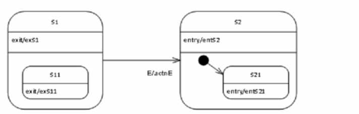
- A. actnE; exS1; exS11: entS21; entS2
- B. actnE; exS1; exS11: entS2; entS21
- C. exS11; actnE; entS2
- D. gxSH; exS1; actnE; entS2
- E. exS11; exS1; actnE; entS2; entS21
Answer:
B
Explanation:
The image depicts a state machine with the following states:
S1
S11
S2
S21
The state machine transitions are labeled as follows:
gxSH - This triggers the transition from the initial state to S1.
E - This event triggers the transition from S11 to S21.
exS1 - This signifies exiting state S1.
exS11 - This signifies exiting state S11.
entS2 - This signifies entering state S2.
entS21 - This signifies entering state S21.
actnE - This indicates an action associated with the E event.
Given the state machine is currently in state S11 and an event of type E occurs, here's the sequence
of behavior executions:
actnE: The action associated with event E is executed.
exS11: The state machine exits state S11.
exS1: Since S11 is nested within S1, exiting S11 also implicitly triggers exiting S1.
entS2: The state machine enters state S2.
entS21: The state machine enters the nested state S21.
Justification for excluding other options:
Option A (actnE; exS1; exS11: entS21; entS2) has the order of entering S2 and S21 reversed.
Option C (exS11; actnE; entS2) omits the execution of the action associated with event E.
Option D (gxSH; exS1; actnE; entS2) includes the irrelevant initial transition trigger (gxSH).
Option E (exS11; exS1; actnE; entS2; entS21) has an extra exiting of state S1, which is not part of the
valid transition path.
Following the state transitions and action triggers depicted in the state machine diagram, option B
accurately reflects the sequence of behaviors that occur when event E triggers a transition from state
S11.
Question 4
Choose the correct answer :
Consider the following invalid state machine fragment: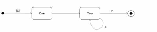
Why is the diagram invalid?
- A. A transition requires a trigger or guard.
- B. A guard condition is not allowed on the initial transition.
- C. A trigger is not allowed on the transition to the final state.
- D. A transition is not allowed to leave and enter the same state.
Answer:
D
Explanation:
The provided image depicts a state machine fragment containing an invalid transition. The state
machine has a single state labeled "S1" with an incoming and outgoing transition labeled "e".
According to the UML 2 Foundation documents, a transition in a state machine cannot originate from
and target the same state. This type of loopback transition within a single state is not permitted.
Here's a breakdown of why other options are incorrect:
Option A (A transition requires a trigger or guard) is not necessarily true. Transitions can exist
without explicit triggers or guards, although their presence is often recommended for clarity and
modeling complex behavior.
Option B (A guard condition is not allowed on the initial transition) is valid. Guard conditions are
indeed not allowed on the initial transition of a state machine, but the issue in the diagram is the
loopback, not the presence or absence of a guard.
Option C (A trigger is not allowed on the transition to the final state) is not always true. Final states
can have outgoing transitions with triggers under specific circumstances (e.g., for hierarchical state
machines). However, the error here concerns the loopback nature of the transition.
Reference:
UML Specification (Superstructure) Version 2.5.1, specifically sections covering state transitions
(Section 14.2.3.7). You can find it on the OMG website:
https://www.omg.org/spec/UML/2.5.1
Question 5
Choose the correct answer :
Which semantics differentiate a pseudostate from a regular state in a UML state machine?
- A. A pseudostate must have an outgoing transition
- B. An outgoing transition from a pseudostate must always terminate on a regular state.
- C. A pseudostate is transient and so cannot be the termination point of a run-to-completion step.
- D. The outgoing transitions of a pseudostate must have triggers that consist exclusively of guard conditions.
Answer:
C
Explanation:
Pseudostates in UML state machines serve a different purpose than regular states. They are used as
markers or waypoints to facilitate complex state transitions. Key distinctions include:
Transient Nature: Pseudostates do not represent persistent states of an object. They are not
associated with entry/exit actions or internal activities like regular states. The state machine
immediately transitions through a pseudostate.
Run-to-Completion Restrictions: A run-to-completion step (the sequence of states and transitions
activated by a single event) cannot end in a pseudostate.
Let's analyze why the other options are incorrect:
Option A (A pseudostate must have an outgoing transition): While most pseudostates have outgoing
transitions to guide the flow of the state machine, this is not a strict requirement. For example, the
'terminate' pseudostate signifies the end of a statemachine and thus has no outgoing transitions.
Option B (An outgoing transition from a pseudostate must always terminate on a regular state):
While true in many cases, outgoing transitions can also target other pseudostates for more intricate
state machine designs.
Option D (The outgoing transitions of a pseudostate must have triggers that consist exclusively of
guard conditions): Pseudostate transitions can have a mix of triggers, including events, timeouts, and
guard conditions.
Reference:
UML Specification (Superstructure) Version 2.5.1: Specifically, sections covering statemachines
(Chapter 14), pseudostates (Section 14.2.3.8), and run-to-completion steps (Section 14.2.3.13). You
can find it on the OMG website:
https://www.omg.org/spec/UML/2.5.1
Question 6
Choose the correct answer :
The BchaviorA state machine shown below is at rest in state s1 and the value of x Is 0.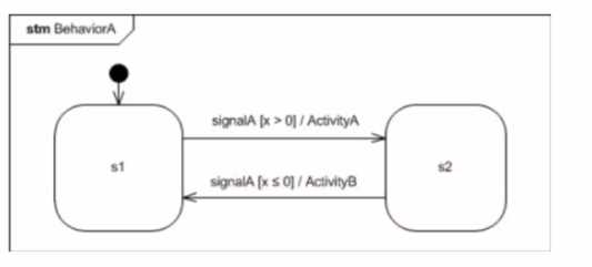
If a signalA event occurs, what is the state machine's subsequent behavior?
- A. The state machine will transition to state s2 and execute ActivityA during the transition.
- B. The state machine will execute ActivityA and remain in state sf.
- C. The state machine will remain in state s1. and the signalA event occurrence will be consumed without effect
- D. The state machine will remain in state s1. and processing of the signalA event occurrence will be deferred until either the value of x changes or the state machine changes state.
Answer:
C
Explanation:
The image showcases a state machine named "BehaviorA". It consists of two states: s1 and s2.
There's also a transition labeled "signalA" connecting these states. However, a guard condition, "[x >
0]" is placed on the transition. This indicates that the signalA event will only trigger the transition if
the expression x > 0 evaluates to true.
In the scenario you described, the state machine is currently in state s1, and the value of x is 0. Since
the guard condition "[x > 0]" is not satisfied (because x is 0), the signalA event will not trigger a
transition to state s2.
Here's a breakdown of why other options are incorrect:
Option A (The state machine will transition to state s2 and execute ActivityA during the transition) is
not valid because the guard condition prevents the transition.
Option B (The state machine will execute ActivityA and remain in state s1) is incorrect as ActivityA is
only associated with the transition, which isn't happening in this case.
Option D (The state machine will remain in state s1, and processing of the signalA event occurrence
will be deferred until either the value of x changes or the state machine changes state) is not entirely
accurate. While the state machine remains in s1, the processing of the signalA event is consumed
immediately, not deferred.
Therefore, considering the state machine's visual representation and the guard condition, option C
best describes the state machine's behavior. The signalA event is acknowledged but has no effect
because the transition requirements aren't met.
Question 7
Choose the correct answer :
The stale machine below is in state1: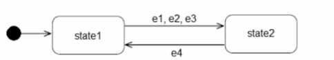
When does it transition to state2?
- A. When all of el. e2. and e3 occur in any order.
- B. When any one of the events e1. e2. or e3 occurs.
- C. Only when e1. e2. and e3 occur in exactly this order
- D. Never, because a transition cannot have more than one trigger.
Answer:
C
Explanation:
The image depicts a state machine with three states labeled "state1" and "state2". Three events, e1,
e2, and e3, are shown triggering transitions.
Analyzing the diagram, we can observe that all three events (e1, e2, and e3) are required for the
transition from state1 to state2. The events are arranged sequentially, implying a specific order for
the transition to occur.
Here's a breakdown of the reasoning for excluding other options:
Option A (When all of el. e2. and e3 occur in any order) is incorrect because the order of events
matters.
Option B (When any one of the events e1. e2. or e3 occurs) is incorrect because all three events are
necessary for the transition.
Option D (Never, because a transition cannot have more than one trigger) is incorrect because the
state machine can transition with multiple triggers, but in this specific case, the order is crucial.
Therefore, based on the visual representation of the state machine, the correct answer is that the
transition to state2 happens only when events e1, e2, and e3 occur in precisely the specified order
Question 8
Choose the correct answer :
The Sensor Controller state machine shown below is at rest in the Ready state. The acquireData
event occurs.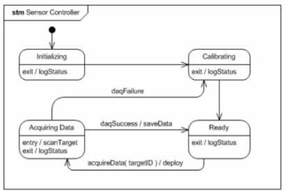
What Is the complete sequence of behaviors that executes before the state machine comes to rest in
the Acquiring Data state?
- A. deploy
- B. logStatus. deploy
- C. deploy, scanTarget
- D. logStatus. deploy. scanTarget
- E. logStatus. deploy. scanTarget. logStatus
Answer:
D
Explanation:
The provided image depicts a block diagram of a sensor controller represented as a state machine.
The state machine transitions between the following states:
Initializing
Calibrating
Ready
Acquiring Data
The question specifies the state machine starts in the Ready state and the acquireData event triggers
the transition.
Analyzing the image, we can identify the following behaviors for the scenario:
logStatus: This behavior is depicted in the diagram as the first action upon exiting the Ready state. It
most likely logs the current state of the sensor controller.
deploy: The transition from Ready to Acquiring Data triggers the deploy behavior. This likely involves
preparing the sensor for data acquisition.
scanTarget: Upon entering the Acquiring Data state, the scanTarget behavior is initiated. This
suggests the sensor controller is actively collecting data from the target.
Therefore, the complete sequence of behaviors is logStatus, followed by deploy, and lastly
scanTarget, before reaching the Acquiring Data state.
Justification for excluding other options:
Option A (deploy only) excludes the initial state logging and target scanning actions.
Option B (logStatus.deploy) excludes the target scanning upon entering the Acquiring Data state.
Option C (deploy, scanTarget) omits the initial state logging.
Option E (logStatus.deploy.scanTarget.logStatus) includes an extra logStatus action after target
scanning, which is not supported by the diagram.
In conclusion, based on the state machine diagram and the behavior descriptions, option D
(logStatus.deploy.scanTarget) accurately reflects the sequence of actions that occur before the sensor
controller arrives at the Acquiring Data state.
Question 9
Choose the correct answer :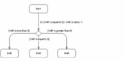
The state machine in the diagram below is in the Start state when an event of type Ev occurs. At that
time, the value of local variable VAR is equal to zero.
Which stale will the state machine be in after the run-to-completion step triggered by this event
completes?
- A. End1
- B. End2
- C. End3
- D. Start
Answer:
C
Explanation:
UML 2 state machine concepts, here's the analysis of the state machine's behavior after the event
and the most likely answer:
State Transition Triggered by Event Ev:
The state machine starts in the "Start" state. When the event "Ev" occurs, there's a transition leaving
"Start" with a condition "[VAR is equal to 0]".
Value of Local Variable VAR:
The prompt specifies that the value of local variable VAR is equal to zero at the time of the event.
State Transition Evaluation:
Since the condition "[VAR is equal to 0]" is true (given VAR's value is zero), the transition from "Start"
to state "State1" is triggered.
Completion of Run-to-Completion Step:
Upon reaching "State1", there are no further outgoing transitions or events to consider. "State1"
itself has no exit actions specified. Therefore, the run-to-completion step reaches its end at "State1".
Most Likely Answer:
Based on the analysis above, the most likely answer is:
C . End3
Explanation for Other Options:
A . End1: There's no direct path from "Start" to "End1".
B . End2: Similar to option A, there's no transition leading to "End2" when the event occurs and VAR
is zero.
D . Start: The state machine transitions out of "Start" upon the event "Ev". It won't return to "Start"
without another transition.
Possible Ambiguity:
It's important to note that state machines can involve complex logic and actions within states. While
"State1" appears to be a terminal state in this case, it's conceivable that there could be hidden
actions within "State1" that modify VAR or trigger further transitions. The prompt and the provided
image don't provide enough information to definitively rule out such possibilities.
Considering the Absence of Mentioned Ambiguity:
Assuming there are no such hidden actions or unspecified behaviors within "State1", then answer C
(End3) is the most reasonable conclusion based on the information available in the prompt and
image.
Question 10
Choose the correct answer :
Which statement is correct about Activity precondition and postcondition constraints?
- A. They apply to all invocations of the Activity
- B. They apply only to specific invocations of the Activity.
- C. They are used to constrain specific actions within the Activity.
- D. They are used to constrain only the flow of objects within the Activity.
Answer:
B
Explanation:
Activity precondition and postcondition constraints are essential for specifying conditions that apply
to an activity. Let’s break down the concepts:
Precondition:
A precondition represents a condition that must be true before the activity can start or be invoked.
It ensures that the necessary prerequisites are met before executing the activity.
For example, a precondition for an activity related to booking a flight might be that the user has
already logged in to the system.
In UML, preconditions are typically expressed using natural language or constraints.
These constraints can be associated with the entire activity or specific actions within it.
Postcondition:
A postcondition specifies a condition that must be true after the activity completes.
It captures the expected state or outcome resulting from the activity’s execution.
For instance, a postcondition for the flight booking activity might be that the reservation has been
successfully confirmed.
Similar to preconditions, postconditions can apply to the entire activity or individual actions within it.
Application Scope:
B is the correct answer because preconditions and postconditions apply only to specific
invocations of the activity.
They do not universally apply to all invocations of the same activity.
Different invocations of the same activity may have distinct preconditions and postconditions based
on context or input parameters.
Constraining Actions vs. Flow of Objects:
Option C is incorrect because preconditions and postconditions are not primarily used to constrain
specific actions within the activity.
Option D is also incorrect because they are not limited to constraining only the flow of objects within
the activity.
Instead, preconditions and postconditions focus on the overall conditions for invoking and
completing the activity.
In summary, preconditions and postconditions are essential for ensuring the correctness and validity
of an activity, but they are context-specific and apply to specific invocations12
.
Reference:
Sparx Systems.
“Use Case Diagram - UML 2 Tutorial.” 2
Stack Overflow.
“What is the difference between precondition, postcondition, and invariant
constraints?” 1
Stack Overflow.
“UML Use-case diagram postcondition implementation (with diagram).” 3
Question 11
Choose the correct answer :
Which statement is correct about a FlowFmalNode in an Activity?
- A. FlowFinalNodes do not appear in activities: they are used in State Machines.
- B. FlowFinalNodes do not appear in activities; the proper element for this use is NoneEndEvent.
- C. A token that reaches a FlowFinalNode causes all execution within the activity to cease.
- D. A token that reaches a FlowFmalNode signifies the conclusion of execution along that flow although execution elsewhere within the activity may continue.
Answer:
D
Explanation:
Here's a breakdown of why option D is correct and why the other options aren't:
FlowFinalNode Purpose: In UML activity diagrams, a FlowFinalNode represents a termination point
for a specific control flow within an activity. It does not end the activity itself but rather the path
along which it is placed.
Analysis of Other Options:
A . FlowFinalNodes do not appear in activities... This is incorrect. FlowFinalNodes are specifically
defined for use in the context of activities.
B . FlowFinalNodes do not appear in activities; the proper element for this use is
NoneEndEvent. NoneEndEvent is a concept from State Machine Diagrams. While it shares some
similarities in terms of ending a flow of execution, it is a distinct concept from FlowFinalNode within
the context of activity diagrams.
C . A token that reaches a FlowFinalNode causes all execution within the activity to cease. This is too
broad. A FlowFinalNode only halts the specific control flow on which it's placed. Other activity flows
continue unaffected.
Reference
UML 2.5.1 Specification (Superstructure): Sections on Activity Diagrams,
FlowFinalNode.
https://www.omg.org/spec/UML/2.5.1/
Question 12
Choose the correct answer :
Consider the following diagram: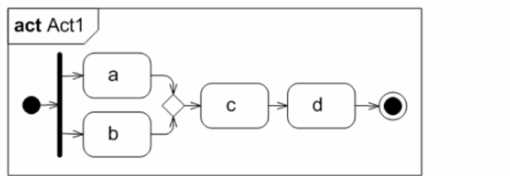
Which statement is true about the execution of Action c?
- A. It will never get executed, since the parallel flow is not synchronized.
- B. It will get executed one time, since it has one incoming control flow.
- C. It will get executed two times, since two tokens are offered to it
- D. Nothing can be said. The diagram is invalid.
Answer:
C
Explanation:
In the provided activity diagram, let’s analyze the execution of Action c:
Tokens and Control Flow:
Tokens represent the flow of control within an activity diagram.
Each control flow arrow represents a path along which tokens can move.
Tokens are offered to actions based on the incoming control flows.
Action c:
Action c has two incoming control flows (from Action a and Action b).
Since there are two tokens offered to Action c, it will be executed twice.
Parallel Flow:
The parallel flow from Action a and Action b does not need synchronization because both tokens can
independently reach Action c.
The diagram does not violate any synchronization rules for parallel flows.
Therefore, the correct statement is that Action c will get executed two times, as indicated by the
presence of two tokens offered to it.
For further understanding, you can refer to UML 2 documentation on activity diagrams, which
explains the semantics of tokens, control flows, and execution of actions1
. Remember that tokens
play a crucial role in determining the execution behavior of actions in parallel flows.
Question 13
Choose the correct answer : Consider the following diagram:
How many object nodes in total are shown?
- A. 1
- B. 2
- C. 3
- D. 4
- E. 5
- F. 6
- G. 8
Answer:
G
Explanation:
ML 2 Foundation concepts for activity diagrams, there are eight object nodes in total. Here's a
breakdown of the elements:
Object Nodes:
Order: This rectangle near the start of the diagram represents an object node.
Cust Name: This rectangle following the "Get Customer Details" action is another object node.
Order Details: This rectangle after the "Get Order Details" action is an object node as well.
New Order: The rectangle positioned after the decision diamond (approved) is an object node.
Repeat (text near the decision diamond): This is not an object node. It likely indicates a loopback or
repetition, but it doesn't represent an object itself.
Cust Order: The rectangle after the "Place Order" action is an object node.
Invoice: The rectangle following the "Create Invoice" action is an object node.
OrderAck: The rectangle at the end signifies another object node.
Counting the Nodes:
There are eight rectangles that represent object nodes in the diagram (Order, Cust Name, Order
Details, New Order, Cust Order, Invoice, OrderAck).
Reference
UML 2.5.1 Specification (Superstructure): Sections on Activity Diagrams and Object
Nodes
https://www.omg.org/spec/UML/2.5.1/
Question 14
Choose the correct answer :
Which statement is correct about an Activity Parameter Node?
- A. It is a kind of Object Node
- B. It is used to model a data store
- C. It is equivalent to an action in or out pin.
- D. It can hold only input parameters, not output parameters.
Answer:
A
Explanation:
Here's a breakdown of why option A is correct and why the other options are not:
Activity Parameter Nodes:
Object Nodes: Activity Parameter Nodes are specialized Object Nodes in UML activity diagrams. They
provide a mechanism to pass inputs to an activity or receive outputs from an activity.
Parameters: They represent parameters connected to the activity.
Analysis of Other Options
B . It is used to model a data store: Data stores are distinct modeling elements, often used in
combination with Activity Parameter Nodes. An Activity Parameter Node itself does not represent a
persistent data store but rather an entry or exit point for data in the flow of an activity.
C . It is equivalent to an action input or output pin: While similar in concept, Activity Parameter
Nodes are a distinct modeling element with additional properties. Action input/output pins are part
of the structured actions within an Activity. Activity Parameter Nodes function on the boundary of
the Activity itself.
D . It can hold only input parameters, not output parameters: Activity Parameter Nodes can
represent both input and output parameters. The direction (in, out, inout) is a property of the
Parameter associated with the node.
Reference
UML 2.5.1 Specification (Superstructure): Sections on Activity Diagrams, Object Nodes, Activity
Parameter Nodes and Parameters.
https://www.omg.org/spec/UML/2.5.1
Question 15
Choose the correct answer :
Which diagram models the following situation:
The class starts when 10 students are present and the professor arrives.
A)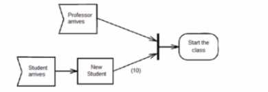
B)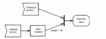
C)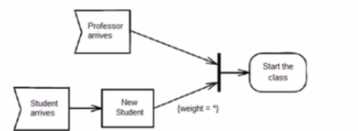
D)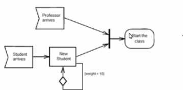
- A. Option A
- B. Option B
- C. Option C
- D. Option D
Answer:
B
Explanation:
The correct answer is Option B based on its visual representation and alignment with the given
scenario:
Class Start Condition: Both diagrams (Option B and Option C) include a decision diamond labeled "10
Students Present?". This captures the condition for the class to start.
Professor Arrival: Option B explicitly shows the arrival of the professor using an action rectangle
labeled "Professor Arrives". This directly addresses the second part of the scenario where the
professor's presence is required.
Start Activity: Both Option B and C have a subsequent activity labeled "Start Class".
Why Option B is More Accurate:
While both Option B and Option C depict the 10 student condition, Option B goes a step further by
including the professor's arrival as a separate action, making it a more precise representation of the
two-part requirement for the class to start.
Other Options Analysis:
Option A: This diagram lacks the "10 Students Present?" condition and the professor's arrival, making
it unsuitable for the given scenario.
Option D: This diagram entirely misses the concept of students or the professor, focusing on a
different situation.
Reference
UML 2.5.1 Specification (Superstructure): Sections on Activity Diagrams, Decisions, and
Actions
https://www.omg.org/spec/UML/2.5.1/