Juniper JN0-664 Exam Questions
Questions for the JN0-664 were updated on : Feb 18 ,2026
Page 1 out of 7. Viewing questions 1-15 out of 96
Question 1
Click the Exhibit button.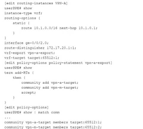
Referring to the exhibit, which statement is correct?
- A. VPN routes are exported with the target:65512:1 and target:65512:2 route targets.
- B. You cannot use the vrf-target and vrf-export statements in the same VRF.
- C. VPN routes with the target:65512:1 and target:65512:2 route targets are imported.
- D. VPN routes are exported with only the target:65512:1 route target
Answer:
A
Explanation:
The exhibit shows the configuration of a VRF (Virtual Routing and Forwarding) instance on a Juniper
PE router. Let's break down the key components:
VRF Configuration (VPN-A)
The instance type is VRF, meaning this is an L3VPN (Layer 3 VPN).
The routing instance contains a static route (10.1.0.0/16 next-hop 10.1.0.1).
The interface ge-0/0/2.0 is assigned to the VRF.
Route Distinguisher (RD): 172.17.20.1:1
VRF-Export Policy: vpn-a-export
VRF-Target: target:65512:1 (This defines which routes will be imported into the VRF).
VRF Export Policy (vpn-a-export)
The vpn-a-export policy adds two BGP communities (route targets) to exported VPN routes:
community add vpn-a-target;
community add vpn-m-target;
accept;
The vpn-a-target community corresponds to target:65512:1.
The vpn-m-target community corresponds to target:65512:2.
Policy-Options (Community Definitions)
community vpn-a-target members target:65512:1;
community vpn-m-target members target:65512:2;
This confirms that routes exported from this VRF will have BOTH target:65512:1 and target:65512:2.
Evaluating the Answer Choices
✅
Option A: "VPN routes are exported with the target:65512:1 and target:65512:2 route targets."
The vpn-a-export policy explicitly adds both vpn-a-target (65512:1) and vpn-m-target (65512:2) to
exported routes.
✅
This is correct.
❌
Option B: "You cannot use the vrf-target and vrf-export statements in the same VRF."
This is incorrect.
Juniper allows the use of both vrf-target and vrf-export in the same VRF:
vrf-target is used for importing routes.
vrf-export defines export policies (which can add additional route targets).
❌
This is incorrect.
❌
Option C: "VPN routes with the target:65512:1 and target:65512:2 route targets are imported."
The vrf-target target:65512:1; statement only controls importing routes.
The import policy does not include target:65512:2, so routes tagged with target:65512:2 alone would
not be imported into this VRF.
❌
This is incorrect.
❌
Option D: "VPN routes are exported with only the target:65512:1 route target."
The export policy (vpn-a-export) clearly adds both 65512:1 and 65512:2.
❌
This is incorrect.
Final Answer:
✅
A. VPN routes are exported with the target:65512:1 and target:65512:2 route targets.
Verification from Juniper Documentation
Juniper MPLS L3VPN Configuration Guide confirms that vrf-target is used for importing, while vrf-
export can be used for exporting multiple route targets.
Juniper Routing Policy Documentation states that export policies can add multiple BGP communities
(route targets).
RFC 4364 (BGP/MPLS IP VPNs) defines the use of route targets for VPN route control.
Question 2
You are configuring schedulers to define the class-of-service properties of output queues. You want
to control packet drops during periods of congestion.
In this scenario, which CoS configuration parameter would be used to accomplish this task?
- A. buffer size
- B. priority
- C. shaping rate
- D. drop profile
Answer:
D
Explanation:
When configuring Class of Service (CoS) properties for output queues, we need to manage packet
drops during periods of congestion. Juniper's CoS framework provides several tools to manage
congestion, including drop profiles, buffer sizes, and scheduling mechanisms. Let’s break down each
option and identify the correct one.
Evaluating the Answer Choices
✅
D. drop profile (Correct Answer)
Why?
A drop profile defines when packets should be dropped based on the queue fill level.
Random Early Detection (RED) or Tail Drop can be used to manage congestion by discarding lower-
priority packets first.
Drop profiles are configured under the scheduler to determine how aggressive packet dropping
should be during congestion.
Example Juniper Configuration:
schedulers {
best-effort {
drop-profile low-drop;
}
}
drop-profiles {
low-drop {
fill-level 80 drop-probability 50;
}
}
fill-level 80 → When the queue reaches 80% full, packet drops begin.
drop-probability 50 → There is a 50% chance of dropping packets once the threshold is reached.
Official Juniper Documentation Reference:
Junos Class of Service Configuration Guide
"A drop profile determines how packets are discarded based on the queue fill level, allowing control
over congestion behavior."
Why the Other Options Are Incorrect?
❌
A. buffer size (Incorrect)
Why?
The buffer size determines how many packets the queue can store before congestion occurs.
A larger buffer can delay drops, but it does not actively control dropping behavior.
It affects latency rather than controlling packet drops.
❌
B. priority (Incorrect)
Why?
Priority controls which queue gets serviced first, not how drops are handled.
Higher priority queues are serviced before lower-priority queues, but this does not prevent
congestion-related drops.
❌
C. shaping rate (Incorrect)
Why?
Shaping limits the maximum transmission rate of the queue.
While shaping helps reduce congestion, it does not control which packets get dropped during
congestion.
Shaping is useful for traffic smoothing, but it does not actively drop packets based on queue fill
levels.
✅
Final Answer:
D. drop profile
Explanation:
Controls packet drops based on queue congestion.
Defines RED (Random Early Detection) or Tail Drop mechanisms.
Directly influences drop probability as the queue fills up.
Official Juniper Reference:
"Drop profiles are used to manage congestion by determining when and how aggressively packets
are dropped based on queue fill level."
Question 3
Refer to the Exhibit: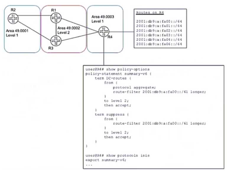
A network designer would like to advertise a single summary route from R4 to IS-IS level 2 neighbors
as shown in the exhibit, but the configuration is not working.
Which three configuration changes will accomplish this task? (Choose three.)
- A. delete protocols isis export summary-v6
- B. set protocols isis import summary-v6
- C. delete policy-options policy-statement summary-v6 term DC-routes from route-filter 2001:db5:a:fa00::/61 longer
- D. set policy-options policy-statement summary-v6 term DC-routes from route-filter 2001:dbS:a:fa00::/6l exact
- E. set policy-options policy-statement summary-v6 term suppress then reject
Answer:
CDE
Question 4
Refer to the exhibit.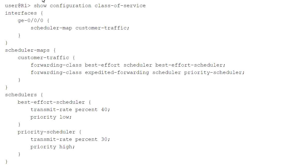
Click the Exhibit button.
Which two statements are correct about the class-of-service configuration shown in the exhibit?
(Choose two.)
- A. Incoming traffic will not be classified because no classifier exists in the configuration.
- B. The best-effort queue can transmit more than 40% of the total bandwidth on the ge-0/0/0 interface, if no other queue is using that bandwidth.
- C. Incoming traffic will be classified using the default classifier.
- D. The best-effort queue can never transmit more than 40% of the total bandwidth on the ge-0/0/0 interface, even if that bandwidth is available.
Answer:
BC
Explanation:
https://www.juniper.net/documentation/us/en/software/junos/traffic-mgmt-qfx/topics/concept/cos-qfx-series-default-scheduling-classification-understanding.html
Question 5
You are using a Layer 3 VPN to connect two customer sites. The VPN routes for the customer
networks appear as hidden in the bgp. 13vpn. o routing table on the PE routers.
What is causing this problem?
- A. The routes use overlapping IP addresses.
- B. There is not an established MPLS LSP between the two PE routers.
- C. There is a routing loop in the service provider backbone.
- D. Route targets are not configured.
Answer:
B
Explanation:
For a Layer 3 VPN to function correctly, an MPLS Label Switched Path (LSP) must be established
between the Provider Edge (PE) routers. The MPLS LSP is necessary for the transport of VPN traffic
across the service provider's backbone network. If the MPLS LSP is not established, the PE routers
cannot forward the VPN traffic properly, causing the routes to be hidden in the BGP routing table.
Here’s a breakdown of why the other options are less likely:
A . The routes use overlapping IP addresses.
Overlapping IP addresses might cause issues with route advertisement and selection, but they would
not typically cause routes to be hidden in the bgp.l3vpn.0 table.
C . There is a routing loop in the service provider backbone.
While routing loops are problematic, they would not specifically cause the routes to be hidden in the
bgp.l3vpn.0 table. Routing loops would more likely result in dropped packets or increased latency.
D . Route targets are not configured.
Incorrect or missing route target configuration would prevent routes from being imported into the
correct VRF, but it would not usually result in the routes being hidden. Instead, they would simply not
appear in the relevant VRF.
Thus, the absence of an established MPLS LSP is the most plausible cause for the routes being
hidden.
Question 6
A router running IS-IS is configured with an ISO address of 49.0001.00a0.c96b.c490.00.
Which part of this address is the system ID?
- A. 00a0.c96b.c490 is the system identifier.
- B. 0001.00a0.c96b.c490 is the system identifier.
- C. c96b.c490 is the system identifier.
- D. c490 is the system identifier.
Answer:
A
Explanation:
In IS-IS (Intermediate System to Intermediate System) routing, each router is identified by a unique
ISO (International Organization for Standardization) address, also known as a Network Entity Title
(NET). The NET consists of three parts:
1. **Area Identifier**: Indicates the area to which the router belongs.
2. **System Identifier**: Uniquely identifies the router within the area.
3. **NSAP Selector (NSEL)**: Typically set to 00 for a router, indicating the Network Service Access
Point.
The format of the ISO address is `49.XXXX.YYYY.YYYY.ZZZZ.ZZZZ.00`, where:
- `49` is the AFI (Authority and Format Identifier) indicating a private address.
- `XXXX` is the Area Identifier.
- `YYYY.YYYY.YYYY` is the System Identifier.
- `ZZZZ.ZZZZ` is the NSAP Selector.
Given the address `49.0001.00a0.c96b.c490.00`:
- **Area Identifier**: `49.0001`
- **System Identifier**: `00a0.c96b.c490`
- **NSAP Selector**: `00`
**Explanation**:
- **A. 00a0.c96b.c490 is the system identifier**:
- Correct. The System Identifier in an ISO address is a 48-bit (6-byte) field used to uniquely identify
the router. In this address, `00a0.c96b.c490` is the correct 6-byte System Identifier.
- **B. 0001.00a0.c96b.c490 is the system identifier**:
- Incorrect. This includes the Area Identifier as part of the System Identifier, which is not correct.
- **C. c96b.c490 is the system identifier**:
- Incorrect. This is only part of the System Identifier. The full System Identifier must be 6 bytes long.
- **D. c490 is the system identifier**:
- Incorrect. This is an incomplete and incorrect part of the System Identifier.
**Conclusion**:
The correct part of the address that represents the System Identifier is:
**A. 00a0.c96b.c490 is the system identifier.**
**Reference**:
- Juniper Networks Documentation on IS-IS: [IS-IS
Configuration](https://www.juniper.net/documentation/en_US/junos/topics/task/configuration/isis-configuring.html)
- ISO/IEC 10589, the IS-IS routing protocol standard.
Question 7
Refer to the exhibit.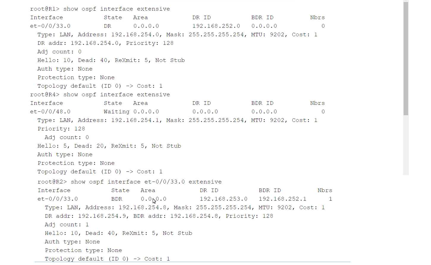
Click the Exhibit button.
You have an OSPF environment. You have recently added a router called R4 that is directly connected
to R1 and R2. You discover that R4 is only peering with R2.
Referring to the exhibit, how would you correct the peering?
- A. Adjust the Priority on R1 to be lower than the Priority on R4.
- B. Change the MTU size on R1 and R2 to be 22 bytes higher than R4's MTU size.
- C. Adjust the Dead Interval on R4 to match the Dead Interval on R1 and R2.
- D. Adjust the Hello Interval on R1 and R2 to match the Hello Interval on R4.
Answer:
D
Question 8
You must alter class-of-service values in packets on the outbound interface of an edge router.
In this scenario, which CoS component allows you to accomplish this task?
- A. output policer
- B. scheduler
- C. rewrite rules
- D. forwarding classes
Answer:
C
Explanation:
Class of Service (CoS) in networking is used to manage traffic by classifying, scheduling, and
sometimes modifying packets to ensure network performance and Quality of Service (QoS). Different
CoS components are used to achieve these goals. Let's analyze each option to determine which CoS
component allows you to alter class-of-service values on the outbound interface of an edge router.
1. **Output Policer**:
- Policing is used to control the rate of traffic sent to or from a network interface. It can drop or
remark traffic that exceeds a certain rate.
- Policing is not typically used to alter CoS values but to enforce traffic limits.
2. **Scheduler**:
- A scheduler is responsible for managing the order in which packets are transmitted out of an
interface based on their CoS markings. It can allocate bandwidth and prioritize traffic.
- The scheduler manages how packets are queued and sent but does not alter the CoS values of
packets.
3. **Rewrite Rules**:
- Rewrite rules are used to modify the CoS values of packets, such as DSCP (Differentiated Services
Code Point) or 802.1p bits, as they exit an interface.
- Rewrite rules can alter the class-of-service values in the packet headers to match the desired
policies of the outbound interface.
- Therefore, rewrite rules are the correct component for altering CoS values on an outbound
interface.
4. **Forwarding Classes**:
- Forwarding classes are used to categorize packets into different traffic classes within a router for
QoS handling.
- They help in defining how packets should be treated by the scheduler but do not directly modify
the CoS values.
**Conclusion**:
To alter class-of-service values in packets on the outbound interface of an edge router, the correct
CoS component to use is:
**C. rewrite rules**
**Reference**:
- Juniper Networks Documentation on CoS: [Class of Service
Overview](https://www.juniper.net/documentation/en_US/junos/topics/concept/class-of-service-overview.html)
- Junos OS CoS Configuration Guide: [Rewrite
Rules](https://www.juniper.net/documentation/en_US/junos/topics/topic-map/class-of-service-rewrite-rules.html)
Question 9
You are configuring a Layer 3 VPN between two sites. You are configuring the vrf-target target :
65100:100 statement in your routing instance.
In this scenario, which two statements describe the vrf-target configuration? (Choose two.)
- A. This value is used to identify BGP routes learned from the local CE device.
- B. This value is used to identify BGP routes learned from the remote PE device.
- C. This value is used to add a target community to BGP routes advertised to the local CE device.
- D. This value is used to add a target community to BGP routes advertised to the remote PE device.
Answer:
BD
Explanation:
The `vrf-target` statement in a Layer 3 VPN configuration is used to control the import and export of
VPN routes by attaching a target community to the routes. This helps in defining which VPN routes
should be imported into or exported from a particular VRF (Virtual Routing and Forwarding) instance.
1. **Understanding VRF Target**:
- The `vrf-target` statement specifies the extended community attributes (route targets) that are
used to control the import and export of routes in a VRF.
- These attributes help in identifying which routes should be shared between different VRFs,
particularly across different PE (Provider Edge) devices.
2. **Statements Analysis**:
- **A. This value is used to identify BGP routes learned from the local CE device.**
- Incorrect. The `vrf-target` attribute is not used to identify routes learned from the local CE
device. It is used to manage routes between PE devices and within the provider's MPLS network.
- **B. This value is used to identify BGP routes learned from the remote PE device.**
- Correct. The `vrf-target` value helps in identifying which routes from remote PE devices should
be imported into the local VRF. It essentially acts as a filter for importing BGP routes with matching
target communities.
- **C. This value is used to add a target community to BGP routes advertised to the local CE
device.**
- Incorrect. Routes advertised to the local CE device do not use the `vrf-target` attribute. Instead,
these routes are typically managed within the local VRF routing table.
- **D. This value is used to add a target community to BGP routes advertised to the remote PE
device.**
- Correct. When advertising routes from the local PE to remote PE devices, the `vrf-target` value is
added to these routes. This target community ensures that the correct routes are shared across the
VPN.
**Conclusion**:
The correct statements about the `vrf-target` configuration in a Layer 3 VPN scenario are:
**B. This value is used to identify BGP routes learned from the remote PE device.**
**D. This value is used to add a target community to BGP routes advertised to the remote PE
device.**
**Reference**:
- Juniper Networks Documentation on VRF Target: [VRF Target
Configuration](https://www.juniper.net/documentation/en_US/junos/topics/topic-map/layer-3-vpns.html)
- MPLS and VPN Architectures by Ivan Pepelnjak and Jim Guichard
Question 10
Refer to the exhibit.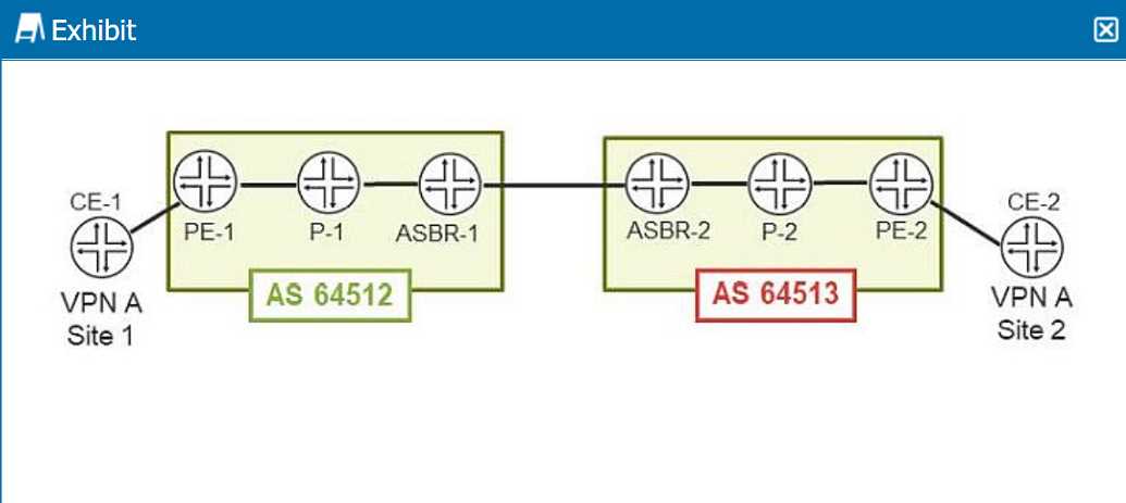
Click the Exhibit hutton.
You are configuring an interprovider Option C Layer 3 VPN to connect two customer sites.
Referring to the exhibit, which three statements are correct? (Choose three.)
- A. ASBR routers maintain the internal routes from its own AS and the loopback addresses from the other AS PEs.
- B. PE routers maintain the internal routes from its own AS, the loopback address from the other AS PEs, and the L3VPN routes.
- C. P routers only maintain the internal routes from their own AS.
- D. P routers maintain the internal routes from its own AS and the loopback address from the other AS PEs.
- E. ASBR routers maintain the internal routes from its own AS, the loopback address from the other AS PEs, and the L3VPN routes.
Answer:
ABC
Explanation:
Interprovider Option C for Layer 3 VPNs involves the use of Autonomous System Boundary Routers
(ASBRs) to exchange labeled VPN-IPv4 routes between different Autonomous Systems (AS). This
option requires BGP sessions between ASBRs, and the VPN routes are carried end-to-end using MPLS
labels. Here’s a detailed analysis of the roles of different routers in this scenario:
1. **ASBR Routers**:
- ASBRs are responsible for exchanging VPN-IPv4 routes between different ASes.
- **A. ASBR routers maintain the internal routes from its own AS and the loopback addresses from
the other AS PEs.**
- Correct. ASBRs maintain routes to internal destinations within their own AS, and they also need
to know the loopback addresses of PEs in the other AS to set up the BGP sessions and MPLS tunnels.
2. **PE Routers**:
- PE routers are responsible for maintaining VPN routes and label information to forward VPN traffic
correctly.
- **B. PE routers maintain the internal routes from its own AS, the loopback address from the other
AS PEs, and the L3VPN routes.**
- Correct. PE routers need to maintain:
- Internal routes within their AS for routing.
- Loopback addresses of other AS PEs for establishing MPLS LSPs.
- L3VPN routes to provide end-to-end VPN connectivity.
3. **P Routers**:
- P routers are the core routers that do not participate in BGP VPN routing but forward labeled
packets based on MPLS labels.
- **C. P routers only maintain the internal routes from their own AS.**
- Correct. P routers maintain the internal routing information to forward packets within the AS and
use MPLS labels for forwarding VPN packets. They do not maintain VPN routes or routes from other
ASes.
4. **Incorrect Statements**:
- **D. P routers maintain the internal routes from its own AS and the loopback address from the
other AS PEs.**
- Incorrect. P routers do not need to maintain the loopback addresses of other AS PEs. They only
maintain internal routing and MPLS label information.
- **E. ASBR routers maintain the internal routes from its own AS, the loopback address from the
other AS PEs, and the L3VPN routes.**
- Incorrect. ASBR routers do not maintain L3VPN routes. They exchange labeled VPN-IPv4 routes
with other ASBRs and forward them to PE routers.
**Conclusion**:
The correct answers are:
**A. ASBR routers maintain the internal routes from its own AS and the loopback addresses from the
other AS PEs.**
**B. PE routers maintain the internal routes from its own AS, the loopback address from the other AS
PEs, and the L3VPN routes.**
**C. P routers only maintain the internal routes from their own AS.**
**Reference**:
- Juniper Networks Documentation on Interprovider VPNs: [Interprovider VPN
Configuration](https://www.juniper.net/documentation/en_US/junos/topics/topic-map/mpls-vpn-interprovider.html)
- MPLS and VPN Architectures, CCIP Edition by Ivan Pepelnjak and Jim Guichard
Question 11
You have an L2VPN connecting two CEs across a provider network. The CEs and provider network are
configured with the default MTU setting. You use the ping command from one
CE to the other CE with a size of 1500 bytes.
In this scenario, which statement is correct when using the ping command?
- A. You expect the ping results to be fragmented.
- B. You expect a silent discard.
- C. You expect an echo reply.
- D. You expect an ICMP message too long error.
Answer:
B
Explanation:
Layer 2 VPNs don’t support fragmentation in the provider network. It is critical that the provider
network supports the largest frame that the CE devices can generate after the MPLS and virtual
routing and forwarding (VRF) labels are added by the PE devices. This example leaves the CE devices
at the default 1500-byte maximum transmission unit (MTU) while configuring the provider core to
support a 4000 byte MTU. This configuration avoids discards by ensuring the CE devices cannot
exceed the MTU in the provider’s network.
Question 12
You have an L2VPN connecting two CEs across a provider network that runs OSPF. You have OSPF
configured on both CEs.
Which two statements are correct in this scenario? (Choose two.)
- A. OSPF neighborship is formed between the CEs and PEs.
- B. The CE and PE OSPF areas can be different.
- C. The CE and PE OSPF areas must match.
- D. OSPF neighborship is formed between the two CEs.
Answer:
BD
Explanation:
In an L2VPN scenario, the provider network connects two customer edge (CE) devices across a Layer
2 virtual private network. Let's analyze how OSPF operates in this setup.
1. **OSPF Neighborship in L2VPN**:
- An L2VPN provides a Layer 2 connection between two sites, making it transparent to Layer 3
protocols like OSPF. This means the CEs can form OSPF adjacencies directly with each other as if they
were on the same local network.
2. **OSPF Configuration on CEs and PEs**:
- **Statement A: OSPF neighborship is formed between the CEs and PEs**:
- Incorrect. In an L2VPN, the provider's network is transparent to the OSPF running on the CEs.
OSPF neighborship forms directly between the CEs, not between the CEs and PEs.
- **Statement B: The CE and PE OSPF areas can be different**:
- Correct. Since OSPF adjacencies form directly between the CEs and not between CEs and PEs, the
OSPF areas on the CEs and PEs can be different. The provider network acts as a transparent bridge,
and OSPF doesn't see the PEs.
- **Statement C: The CE and PE OSPF areas must match**:
- Incorrect. As noted above, because the OSPF neighborship forms directly between the CEs, the
OSPF areas on the CEs and PEs do not need to match.
- **Statement D: OSPF neighborship is formed between the two CEs**:
- Correct. The L2VPN makes the connection between the two CEs appear as a direct Layer 2 link,
allowing them to form an OSPF adjacency directly.
**Conclusion**:
Given the above analysis, the correct statements are:
**B. The CE and PE OSPF areas can be different.**
**D. OSPF neighborship is formed between the two CEs.**
**Reference**:
- Juniper Networks Documentation on L2VPNs: [Configuring Layer 2
VPNs](https://www.juniper.net/documentation/en_US/junos/topics/task/configuration/layer-2-vpns-configuring.html)
- OSPF Configuration Guide: [Junos OS OSPF
Configuration](https://www.juniper.net/documentation/en_US/junos/topics/concept/ospf-routing-overview.html)
Question 13
Refer to the exhibit.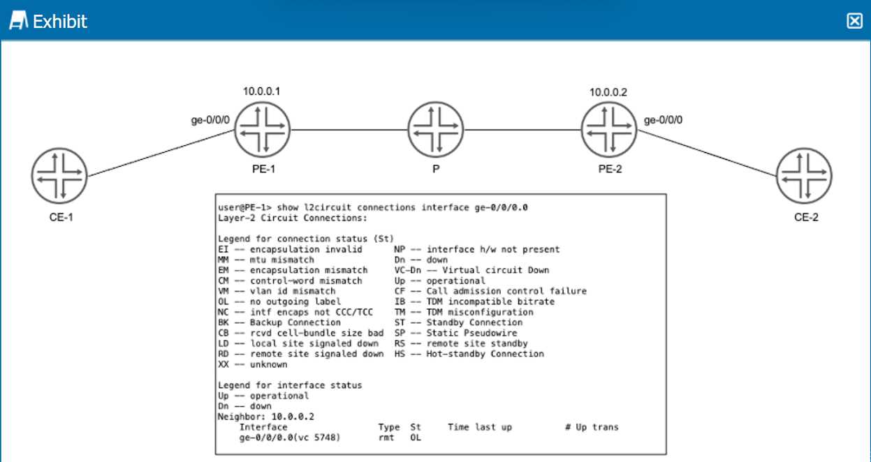
Click the Exhibit button.
PE-1 and PE-2 are configured with LDP-signaled pseudowires to provide connectivity between CE-1
and CE-2. You notice no connectivity exists between CE-1 and CE-2.
Referring to the exhibit, which two statements describe potential causes for this fault? (Choose two.)
- A. The VC IDs are mismatched.
- B. There is no LSP configured from PE-1 to PE-2.
- C. Interface ge-0/0/0 on PE-1 is down.
- D. There is no LSP configured from PE-2 to PE-1.
Answer:
AD
Question 14
Which two statements about IS-IS are correct? (Choose two.)
- A. PSNPs are used to acknowledge a received LSP.
- B. CSNPs are used to acknowledge a received LSP.
- C. CSNPs are used to request a missing LSP.
- D. PSNPs are used to request a missing LSP.
Answer:
AD
Explanation:
Intermediate System to Intermediate System (IS-IS) is a link-state routing protocol used to move
information efficiently within a computer network. It uses a series of Protocol Data Units (PDUs) to
manage the network's topology and ensure consistency across all routers in the network. Specifically,
Link State PDUs (LSPs), Complete Sequence Number PDUs (CSNPs), and Partial Sequence Number
PDUs (PSNPs) play crucial roles in this process.
1. **PSNPs (Partial Sequence Number PDUs)**:
- **Acknowledge a received LSP**: PSNPs are used to acknowledge the receipt of LSPs. When a
router receives an LSP, it sends a PSNP back to the sender to confirm that the LSP has been received.
- **Request a missing LSP**: PSNPs are also used to request missing LSPs. If a router identifies a
missing LSP based on sequence numbers, it can send a PSNP to request the specific LSP from its
neighbors.
2. **CSNPs (Complete Sequence Number PDUs)**:
- **Summarize LSPs**: CSNPs are used to summarize all the LSPs known to a router. They are
typically sent at regular intervals to provide a complete list of LSPs in a database. They are not used
to acknowledge or request specific LSPs but provide an overview of all LSPs for database
synchronization.
Based on this understanding, let's evaluate the statements:
- **A. PSNPs are used to acknowledge a received LSP.**
- Correct. PSNPs serve the purpose of acknowledging LSPs received from other routers.
- **B. CSNPs are used to acknowledge a received LSP.**
- Incorrect. CSNPs are not used for acknowledging LSPs; they are used to provide a summary of all
LSPs.
- **C. CSNPs are used to request a missing LSP.**
- Incorrect. CSNPs are not used to request missing LSPs; this is the role of PSNPs.
- **D. PSNPs are used to request a missing LSP.**
- Correct. PSNPs are used to request specific missing LSPs when a router detects that it is missing
information.
**Conclusion**:
The correct statements about IS-IS are:
**A. PSNPs are used to acknowledge a received LSP.**
**D. PSNPs are used to request a missing LSP.**
**Reference**:
- Juniper Networks Documentation on IS-IS: [IS-IS
Overview](https://www.juniper.net/documentation/en_US/junos/topics/concept/is-is-routing-overview.html)
- RFC 1195, Use of OSI IS-IS for Routing in TCP/IP and Dual Environments: [RFC
1195](https://tools.ietf.org/html/rfc1195) which details the operation and use of IS-IS, including the
roles of PSNPs and CSNPs.
Question 15
Which two statements are correct regarding the PIM DR in a PIM-SM domain? (Choose two.)
- A. The source DR sends PIM register messages from the source network to the RP.
- B. If the DR priorities match, the router with the lowest IP address is selected as the DR.
- C. The receiver DR sends PIM join and PIM prune messages from the receiver network toward the RP.
- D. By default, PIM DR election is performed on point-to-point links.
Answer:
AC
Explanation:
In PIM-SM (Protocol Independent Multicast - Sparse Mode), the Designated Router (DR) plays a
crucial role in multicast forwarding. The DR is responsible for various tasks depending on whether it
is connected to the source or the receiver. Let's analyze each statement regarding the PIM DR in a
PIM-SM domain.
1. **Statement A: The source DR sends PIM register messages from the source network to the RP.**
- Correct. In PIM-SM, the DR on the source's local network is responsible for encapsulating
multicast packets in PIM Register messages and sending them to the Rendezvous Point (RP). This
process ensures that the RP is aware of active sources.
2. **Statement B: If the DR priorities match, the router with the lowest IP address is selected as the
DR.**
- Incorrect. The correct rule is that if the DR priorities match, the router with the **highest** IP
address is selected as the DR. The election process first compares priorities; if priorities are equal,
the IP addresses are compared to select the DR.
3. **Statement C: The receiver DR sends PIM join and PIM prune messages from the receiver
network toward the RP.**
- Correct. In PIM-SM, the DR on the receiver's local network sends PIM Join messages toward the
RP to join the multicast distribution tree. Similarly, it sends PIM Prune messages to leave the tree
when there are no interested receivers.
4. **Statement D: By default, PIM DR election is performed on point-to-point links.**
- Incorrect. By default, PIM DR election is performed on multi-access networks (e.g., Ethernet). On
point-to-point links, there is no need for a DR election as there are only two routers involved.
**Conclusion**:
The correct statements regarding the PIM DR in a PIM-SM domain are:
**A. The source DR sends PIM register messages from the source network to the RP.**
**C. The receiver DR sends PIM join and PIM prune messages from the receiver network toward the
RP.**
**Reference**:
- Juniper Networks Documentation on PIM-SM: [PIM-SM
Overview](https://www.juniper.net/documentation/en_US/junos/topics/concept/pim-sparse-mode-overview.html)
- RFC 7761, Protocol Independent Multicast - Sparse Mode (PIM-SM): [RFC
7761](https://tools.ietf.org/html/rfc7761) which details the PIM-SM protocol, including DR roles and
election procedures.