Juniper JN0-480 Exam Questions
Questions for the JN0-480 were updated on : Feb 18 ,2026
Page 1 out of 5. Viewing questions 1-15 out of 65
Question 1
A member of your organization made changes to a predefined interface map using Juniper Apstra.
Which two statements are correct in this scenario? (Choose two.)
- A. Changes to interface maps in the global catalog do not affect interface maps that have already been imported into blueprint catalogs
- B. Any changes made to predefined interface maps are discarded when Apstra is upgraded.
- C. Changes made to predefined interface maps will not have an impact on the Apstra software.
- D. Changes to interface maps in the global catalog will raise anomalies that may need to be addressed at the next commit.
Answer:
AB
Explanation:
According to the Juniper documentation1
, an interface map is a configuration template that maps
interfaces between logical devices and physical hardware devices (represented with device profiles)
while adhering to vendor specifications. An interface map can be either predefined or custom. A
predefined interface map is one that ships with Apstra software and supports most qualified Juniper
devices. A custom interface map is one that is created by the user to meet specific requirements. An
interface map can be stored in either the global catalog or the blueprint catalog. The global catalog
contains all the interface maps that are available for use in any blueprint. The blueprint catalog
contains the interface maps that are imported from the global catalog and used in a specific
blueprint.
When a member of your organization makes changes to a predefined interface map, the following
statements are correct:
Changes to interface maps in the global catalog do not affect interface maps that have already been
imported into blueprint catalogs. This means that the existing blueprints that use the original version
of the interface map will not be impacted by the changes. However, if you want to use the updated
version of the interface map in a new or existing blueprint, you need to import it again from the
global catalog.
Any changes made to predefined interface maps are discarded when Apstra is upgraded. This means
that the changes will not be preserved across different versions of Apstra software. If you want to
retain a customized interface map through Apstra upgrades, you need to clone the predefined
interface map, give it a unique name, and customize it instead of changing the predefined one
directly.
Therefore, the correct answer is A and B. Changes to interface maps in the global catalog do not
affect interface maps that have already been imported into blueprint catalogs and any changes made
to predefined interface maps are discarded when Apstra is upgraded. Reference:
Edit Interface Map |
Apstra 4.2 | Juniper Networks
Question 2
Exhibit.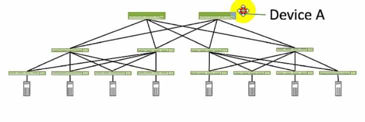
Referring to the exhibit, which role does Device A serve in an IP fabric?
- A. leaf
- B. spine
- C. super spine
- D. server
Answer:
B
Explanation:
Device A serves as a spine in an IP fabric. An IP fabric is a network architecture that uses a spine-leaf
topology to provide high performance, scalability, and reliability for data center networks. A spine-
leaf topology consists of two layers of devices: spine devices and leaf devices. Spine devices are the
core devices that interconnect all the leaf devices using equal-cost multipath (ECMP) routing. Leaf
devices are the edge devices that connect to the servers, storage, or other network devices. In the
exhibit, Device A is connected to four leaf devices using multiple links, which indicates that it is a
spine device. The other options are incorrect because:
A) leaf is wrong because a leaf device is an edge device that connects to the servers, storage, or
other network devices. In the exhibit, Device A is not connected to any servers, storage, or other
network devices, but only to four leaf devices, which indicates that it is not a leaf device.
C) super spine is wrong because a super spine device is a higher-level device that interconnects
multiple spine devices in a large-scale IP fabric. A super spine device is typically used when the
number of leaf devices exceeds the port density of a single spine device. In the exhibit, Device A is
not connected to any other spine devices, but only to four leaf devices, which indicates that it is not a
super spine device.
D) server is wrong because a server device is a compute or storage device that connects to a leaf
device in an IP fabric. A server device is typically the end host that provides or consumes data in the
network. In the exhibit, Device A is not connected to any leaf devices, but only to four leaf devices,
which indicates that it is not a server device. Reference:
IP Fabric Underlay Network Design and Implementation
IP Fabric Overview
IP Fabric Architecture
Question 3
Which two actions are required during Juniper Apstra's deploy phase? (Choose two.)
- A. Assign device profiles to the blueprint.
- B. Assign user roles to the blueprint.
- C. Assign interlace maps to the blueprint.
- D. Assign resources to the blueprint.
Answer:
AD
Explanation:
The deploy phase is the final step in the Juniper Apstra data center fabric design and deployment
process. In this phase, you apply the Apstra-rendered configuration to the devices and verify the
intent of the blueprint.
Based on the web search results, we can infer the following actions are
required during the deploy phase12
:
Assign device profiles to the blueprint. This action associates a specific vendor model to each logical
device in the blueprint. Device profiles contain extensive hardware model details, such as form
factor, ASIC, CPU, RAM, ECMP limit, and supported features. Device profiles also define how
configuration is generated, how telemetry commands are rendered, and how configuration is
deployed on a device.
Device profiles enable the Apstra system to render and deploy the
configuration according to the Apstra Reference Design34
.
Assign resources to the blueprint. This action allocates the physical devices, IP addresses, VLANs, and
ASNs to the logical devices, networks, and routing zones in the blueprint. Resources can be assigned
manually or automatically by the Apstra system.
Assigning resources ensures that the blueprint has
all the necessary elements to generate the configuration and deploy the fabric5
.
Assign user roles to the blueprint. This action is not required during the deploy phase. User roles are
defined at the system level, not at the blueprint level. User roles determine the permissions and
access levels of different users in the Apstra system. User roles can be system-defined or custom-
defined .
Assign interface maps to the blueprint. This action is not required during the deploy phase. Interface
maps are defined at the design phase, not at the deploy phase. Interface maps are objects that map
the logical interfaces of a logical device to the physical interfaces of a device profile. Interface maps
enable the Apstra system to generate the correct interface configuration for each device in the fabric
. Reference:
Deploy
Deploy Device
Device Profiles
Juniper Device Profiles
Resources
Question 4
Exhibit.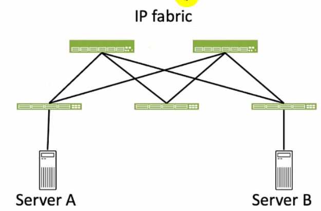
Referring to the exhibit, how many broadcast domains will an Ethernet frame pass through when
traversing the IP fabric from Server A to Server B?
- A. 1
- B. 4
- C. 2
- D. 3
Answer:
C
Explanation:
Referring to the exhibit, the image shows a simplified diagram of an IP fabric network connecting
two servers, labeled as Server A and Server B. The IP fabric is a network architecture that uses a Clos
topology to provide high bandwidth, low latency, and scalability for data center networks.
The IP
fabric consists of spine and leaf devices that use BGP as the routing protocol and VXLAN as the
overlay technology1
.
A broadcast domain is a logical portion of a network where any device can directly transmit
broadcast frames to other devices at the data link layer (OSI Layer 2). A broadcast frame is a frame
that has a destination MAC address of all ones (FF:FF:FF:FF:FF:FF), which means that it is intended for
all devices in the same broadcast domain.
A broadcast domain is usually bounded by a router, which
does not forward broadcast frames to other networks2
.
In the exhibit, there are two broadcast domains that an Ethernet frame will pass through when
traversing the IP fabric from Server A to Server B. The first broadcast domain is the one that contains
Server A and the leaf device that it is connected to. The second broadcast domain is the one that
contains Server B and the leaf device that it is connected to. The IP fabric itself is not a broadcast
domain, because it uses IP routing and VXLAN encapsulation to transport the Ethernet frames over
the Layer 3 network. Therefore, the statement C is correct in this scenario.
The following three statements are incorrect in this scenario:
A) 1. This is not true, because there are not one, but two broadcast domains that an Ethernet frame
will pass through when traversing the IP fabric from Server A to Server B. The IP fabric itself is not a
broadcast domain, because it uses IP routing and VXLAN encapsulation to transport the Ethernet
frames over the Layer 3 network.
B) 4. This is not true, because there are not four, but two broadcast domains that an Ethernet frame
will pass through when traversing the IP fabric from Server A to Server B. The spine devices and the
leaf devices that are not connected to the servers are not part of the broadcast domains, because
they use IP routing and VXLAN encapsulation to transport the Ethernet frames over the Layer 3
network.
D) 3. This is not true, because there are not three, but two broadcast domains that an Ethernet frame
will pass through when traversing the IP fabric from Server A to Server B. The IP fabric itself is not a
broadcast domain, because it uses IP routing and VXLAN encapsulation to transport the Ethernet
frames over the Layer 3 network.
Reference:
IP Fabric Overview
Broadcast Domain - NetworkLessons.com
Question 5
What is the purpose of an interface map in Juniper Apstra?
- A. An interface map associates a logical device with a device profile.
- B. An interface map specifies a connection between the interfaces of two devices.
- C. An interface map specifies the number of ports and the port speeds of a logical device
- D. An interface map specifies the connections between racks in a template.
Answer:
B
Explanation:
According to the Juniper documentation1
, an interface map is a configuration template that maps
interfaces between logical devices and physical hardware devices (represented with device profiles)
while adhering to vendor specifications. An interface map specifies a connection between the
interfaces of two devices, such as a leaf and a spine, a leaf and a server, or a leaf and an external
gateway. An interface map can also specify port transformations, such as breaking out a 40 GbE port
into four 10 GbE ports, or disabling unused ports. An interface map can be used to achieve the
intended network configuration rendering and to enable features such as LAG, ESI-LAG, or MLAG.
Therefore, the correct answer is B. An interface map specifies a connection between the interfaces of
two devices. Reference:
Interface Maps (Datacenter Design)
Question 6
You have a virtual network that needs controlled access to other virtual networks in the same routing
zone. Using the Juniper Apstra Ul. which feature would be used to accomplish this task?
- A. interface policy
- B. anti-affinity policy
- C. routing policy
- D. security policy
Answer:
D
Explanation:
A security policy is the feature that would be used to accomplish the task of controlling access to
other virtual networks in the same routing zone using the Juniper Apstra UI. A security policy allows
you to define rules that specify which traffic is allowed or denied between different virtual networks,
IP endpoints, or routing zones. A security policy can be applied to one or more virtual networks in
the same routing zone, and it can use various criteria to match the traffic, such as source and
destination IP addresses, protocols, ports, or tags. A security policy can also support DHCP relay,
which enables the forwarding of DHCP requests from one virtual network to another. The other
options are incorrect because:
A) interface policy is wrong because an interface policy is a feature that allows you to configure the
interface parameters for the devices in a blueprint, such as interface names, speeds, types, or
descriptions. An interface policy does not affect the access control between different virtual
networks in the same routing zone.
B) anti-affinity policy is wrong because an anti-affinity policy is a feature that allows you to prevent
certain devices or logical devices from being placed in the same rack or leaf pair in a blueprint. An
anti-affinity policy is used to enhance the availability and redundancy of the network, not to control
the access between different virtual networks in the same routing zone.
C) routing policy is wrong because a routing policy is a feature that allows you to configure the
routing parameters for the devices in a blueprint, such as routing protocols, autonomous system
numbers, route filters, or route maps. A routing policy does not affect the access control between
different virtual networks in the same routing zone, unless the routing policy is used to filter or
modify the routes exchanged between different routing zones. Reference:
Security Policy
Interface Policy
Anti-Affinity Policy
Routing Policy
Question 7
What are two system-defined user roles that are available in Juniper Apstra? (Choose two.)
- A. authorized
- B. root
- C. viewer
- D. user
Answer:
CD
Explanation:
Juniper Apstra provides four system-defined user roles that are available in the Apstra GUI
environment.
They are: administrator, device_ztp, viewer, and user1
. Based on the web search
results, we can infer the following statements:
viewer: This role includes permissions to only view various elements in the Apstra system, such as
blueprints, devices, design, resources, external systems, platform, and others.
Users with this role
cannot create, edit, or delete any element12
.
user: This role includes permissions to view and edit various elements in the Apstra system, such as
blueprints, devices, design, resources, external systems, platform, and others.
Users with this role
cannot create or delete any element12
.
authorized: This is not a system-defined user role in Juniper Apstra.
It is a term used to describe users
who have been authenticated by an external system, such as LDAP, Active Directory, TACACS+, or
RADIUS3
.
root: This is not a system-defined user role in Juniper Apstra. It is a term used to describe the
superuser account on a Linux system, which has full access to all commands and files. Creating a user
in the Apstra GUI does not provide that user access to the Apstra platform via SSH.
To access the
Apstra platform via SSH, you must create a local Linux system user4
. Reference:
User / Role Management Introduction
User/Role Management (Platform)
AAA Providers
User Profile Management
Question 8
You want to make a widget appear on the main dashboard in Juniper Apstr
a. In this scenario, which statement is correct?
- A. When creating the widget, select the Add to Blueprint Dashboard option.
- B. On the blueprint dashboard, click on the Add Widget option.
- C. Widgets automatically appear on the blueprint dashboard.
- D. Set the Default toggle switch to On for the desired widget.
Answer:
D
Explanation:
In Juniper Apstra, a widget is a graphical element that displays data from an intent-based analytics
(IBA) probe. A widget can be used to monitor different aspects of the network and raise alerts to any
anomalies. A widget can be viewed by itself or added to an analytics dashboard.
A dashboard is a
collection of widgets that can be customized and organized according to the user’s preference1
.
The main dashboard in Juniper Apstra is the blueprint dashboard, which is the default view that
shows the network information and configuration for the active blueprint. A blueprint is a logical
representation of the network design and intent.
The blueprint dashboard can display the system-
generated dashboards, the user-generated dashboards, and the individual widgets that are relevant
to the network2
.
To make a widget appear on the main dashboard in Juniper Apstra, the user needs to set the Default
toggle switch to On for the desired widget. This will add the widget to the blueprint dashboard,
where it can be viewed along with other network information.
The user can also remove the widget
from the blueprint dashboard by setting the Default toggle switch to Off for the widget3
. Therefore,
the statement D is correct in this scenario.
The following three statements are incorrect in this scenario:
When creating the widget, select the Add to Blueprint Dashboard option. This is not true, because
there is no such option when creating a widget in Juniper Apstra.
The user can only select the widget
type, the probe, and the display mode when creating a widget4
.
To add the widget to the blueprint
dashboard, the user needs to set the Default toggle switch to On for the widget after creating it3
.
On the blueprint dashboard, click on the Add Widget option. This is not true, because there is no
such option on the blueprint dashboard in Juniper Apstra.
The user can only view, edit, or delete the
existing widgets and dashboards on the blueprint dashboard2
.
To add a widget to the blueprint
dashboard, the user needs to set the Default toggle switch to On for the widget from the widgets
table view3
.
Widgets automatically appear on the blueprint dashboard. This is not true, because widgets do not
automatically appear on the blueprint dashboard in Juniper Apstra.
The user needs to manually add
the widgets to the blueprint dashboard by setting the Default toggle switch to On for the widgets
that they want to see on the blueprint dashboard3
.
The only exception is the widgets that are part of
the system-generated dashboards, which are automatically created and added to the blueprint
dashboard based on the state of the active blueprint2
.
Reference:
Widgets Overview
Blueprint Summaries and Dashboard
Widgets Introduction
Create Widget
Question 9
Using Juniper Apstr
a. which component is defined in a template?
- A. the leaf-to-spine interconnection
- B. the speed of the links between the spine devices and the leaf devices
- C. the number of spine devices in a topology
- D. the definition of IP pools
Answer:
A
Explanation:
According to the Juniper documentation1
, a template is a configuration template that defines a
network’s policy intent and structure. A template can be either rack-based or pod-based, depending
on the type and number of racks and pods in the network design. A template includes the following
details:
Policies: These are the parameters that apply to the entire network, such as the overlay control
protocol, the ASN allocation scheme, and the underlay type.
Structure: This is the physical layout of the network, such as the type and number of racks, pods,
spines, and leaves. The structure also defines the leaf-to-spine interconnection, which is the number
and type of links between the leaf and spine devices. The leaf-to-spine interconnection can be either
single or dual, depending on the redundancy and bandwidth requirements.
Therefore, the correct answer is A. the leaf-to-spine interconnection. This is a component that is
defined in a template, as it determines the physical connectivity of the network. The speed of the
links, the number of spine devices, and the definition of IP pools are not components that are
defined in a template, as they are either derived from the device profiles, the resource pools, or the
blueprint settings. Reference:
Templates Introduction | Apstra 4.2 | Juniper Networks
Question 10
Which attribute enables Juniper Apstra to scale and manage thousands of devices with a single
server instance?
- A. Apstra is installed as a cloud resource.
- B. Apstra is based on NGINX.
- C. Apstra is available as an OVA.
- D. Apstra is a distributed state system.
Answer:
D
Explanation:
The attribute that enables Juniper Apstra to scale and manage thousands of devices with a single
server instance is that Apstra is a distributed state system. This means that Apstra uses a graph
database to store the network topology and configuration data in a distributed and replicated
manner across multiple server nodes. This allows Apstra to handle large-scale networks with high
performance, reliability, and availability. Apstra also uses a stateful orchestration engine that ensures
the network state is always consistent with the intent of the blueprint, which is the logical
representation of the network design and behavior. Apstra can automatically detect and resolve any
discrepancies between the desired and actual network state, as well as handle any changes or
failures in the network. The other options are incorrect because:
A) Apstra is installed as a cloud resource is wrong because Apstra can be installed either as a cloud
resource or as an on-premises resource. Apstra is available as a virtual machine image that can be
deployed on various hypervisors, such as VMware ESXi, QEMU/KVM, Microsoft Hyper-V, or Oracle
VirtualBox. Apstra can also be deployed on public cloud platforms, such as Amazon Web Services
(AWS) or Microsoft Azure. However, the installation method does not affect the scalability of Apstra,
which is determined by the distributed state system architecture.
B) Apstra is based on NGINX is wrong because Apstra is not based on NGINX, but on Python and
Django. NGINX is a web server and reverse proxy that Apstra uses to serve the web user interface
and the REST API. However, NGINX is not the core component of Apstra, and it does not affect the
scalability of Apstra, which is determined by the distributed state system architecture.
C) Apstra is available as an OVA is wrong because Apstra is available as an OVF, not an OVA. An OVF
(Open Virtualization Format) is a standard format for packaging and distributing virtual machine
images. An OVA (Open Virtual Appliance) is a single file that contains the OVF and the virtual disk
images. Apstra provides an OVF file that can be imported into various hypervisors, such as VMware
ESXi, QEMU/KVM, Microsoft Hyper-V, or Oracle VirtualBox. However, the availability of Apstra as an
OVF does not affect the scalability of Apstra, which is determined by the distributed state system
architecture. Reference:
JUNIPER APSTRA ARCHITECTURE
Apstra Server Requirements/Reference
Juniper Networks Apstra 4.0 enhances the experience of users and operators
Question 11
Within Managed Devices in the Juniper Apstra Ul, you notice that several devices have the OOS-
Quarantined status. The devices cannot be added to any blueprint. Which action would solve this
problem?
- A. Acknowledge the device.
- B. Fix the hardware issues with the quarantined devices.
- C. Install the agent, even though connectivity is established.
- D. Upload a new pristine configuration.
Answer:
A
Explanation:
When an agent installation is successful, devices are placed into the Out of Service Quarantined
(OOS-QUARANTINED) state using the Juniper Apstra UI. This state means that the device is not yet
managed by Apstra and has not been assigned to any blueprint. The device configuration at this
point is called Pristine Config. To make the device ready for use in a blueprint, you need to
acknowledge the device, which is a manual action that confirms the device identity and
ownership.
Acknowledging the device changes its status to Out of Service Ready (OOS-
READY)12
. Reference:
Managing Devices
AOS Device Configuration Lifecycle
Question 12
What is the purpose of a Juniper Apstra rack?
- A. It stores information on how pods connect to super spines.
- B. It stores information on how leaf nodes connect to generic devices
- C. It stores IP address and ASN pool information.
- D. It stores device port data rates and vendor information.
Answer:
B
Explanation:
A Juniper Apstra rack is a physical entity that contains one or more network devices, such as leaf
nodes, access switches, or generic systems. A rack is used to organize and manage the network
devices in the Apstra software application. A rack has the following characteristics:
It stores information on how leaf nodes connect to generic devices. This is because a rack can include
generic systems, which are devices that are not managed by Juniper Apstra, but are connected to the
network. A generic system can be a server, a firewall, a load balancer, or any other device that has a
network interface.
A rack stores the information on how the leaf nodes, which are the devices that
provide access to the end hosts, connect to the generic devices, such as the port number, the link
speed, the LAG mode, and the roles1
.
It has a rack type, which defines the type and number of leaf devices, access switches, and/or generic
systems that are used in the rack. A rack type is a resource that is created in the data center design
phase, and it does not specify the vendor or the model of the devices.
A rack type can be predefined
or custom-made, and it can be used to create multiple racks with the same structure and
configuration2
.
It has a rack build, which assigns the specific vendor and model of the devices to the rack. A rack
build is created in the staged phase, and it uses the rack type as a template.
A rack build can also
assign the resources, such as the IP addresses, the ASNs, and the VNIs, to the devices in the rack3
.
It has a rack deployment, which applies the network configuration and services to the devices in the
rack. A rack deployment is performed in the active phase, and it uses the rack build as a reference.
A
rack deployment can also monitor the network performance and compliance of the devices in the
rack4
.
The following three statements are incorrect in this scenario:
It stores information on how pods connect to super spines. This is not true, because a rack does not
store any information on the pod or the super spine level of the network. A pod is a cluster of leaf
and spine devices that form a 3-stage Clos topology, and a super spine is a device that connects
multiple pods in a 5-stage Clos topology.
A rack only stores information on the leaf and the access
level of the network1
.
It stores IP address and ASN pool information. This is not true, because a rack does not store any
information on the IP address and ASN pools. IP address and ASN pools are resources that are
created in the data center design phase, and they contain a range of IP addresses and ASNs that can
be assigned to the devices and the virtual networks.
A rack only uses the IP address and ASN pools to
assign the resources to the devices in the rack build2
.
It stores device port data rates and vendor information. This is not true, because a rack does not
store any information on the device port data rates and vendor information. The device port data
rates and vendor information are specified in the rack build, which assigns the specific vendor and
model of the devices to the rack.
A rack only uses the rack build to apply the network configuration
and services to the devices in the rack deployment3
.
Reference:
Racks (Staged)
Rack Types (Datacenter Design)
Rack Builds (Staged)
Racks (Active)
Question 13
You use Juniper Apstra to enable a new VXLAN virtual network.
Which two components would be automatically derived in this situation? (Choose two.)
- A. IP subnet
- B. VLAN-ID
- C. VXLAN VNI
- D. Route Zone
Answer:
AC
Explanation:
According to the Juniper documentation1
, a VXLAN virtual network is a collection of Layer 2
forwarding domains that span multiple racks in a fabric. A VXLAN virtual network requires a name
and a VXLAN network identifier (VNI), which is a 24-bit number that identifies the virtual network.
The VNI can be either explicitly assigned or auto-assigned from a resource pool. A VXLAN virtual
network can also have Layer 3 connectivity, which enables routing between different VNIs within a
routing zone. A routing zone is an L3 domain that isolates the IP traffic of different tenants. A routing
zone can have one or more VNIs associated with it. To enable Layer 3 connectivity, a VXLAN virtual
network needs an IP subnet, which is a range of IP addresses that can be assigned to the hosts in the
virtual network. The IP subnet can be either explicitly assigned or auto-assigned from a resource
pool. Therefore, the correct answer is A and C. IP subnet and VXLAN VNI are two components that
would be automatically derived when enabling a new VXLAN virtual network using Juniper
Apstra. Reference:
Virtual Networks | Apstra 4.1 | Juniper Networks
Question 14
Which protocol is used to advertise EVPN routes?
- A. OSPF
- B. BGP
- C. IS-IS
- D. RIP
Answer:
B
Explanation:
BGP is the protocol used to advertise EVPN routes. EVPN routes are a new type of BGP network layer
reachability information (NLRI) that carry MAC address and IP prefix information for Ethernet VPNs.
EVPN routes are exchanged between PEs using BGP multiprotocol extensions (MP-BGP) over MPLS,
VXLAN, SR, or SRv6 tunnels. EVPN routes enable PEs to learn the reachability of MAC addresses and
IP prefixes of different sites within the same EVPN instance. EVPN routes also support various
features such as fast convergence, redundancy, aliasing, and inter-subnet routing. The other options
are incorrect because:
A) OSPF is wrong because OSPF is an interior gateway protocol (IGP) that is used to advertise IP
routes within an autonomous system. OSPF is not used to advertise EVPN routes, which are a type of
BGP NLRI that carry MAC address and IP prefix information for Ethernet VPNs.
C) IS-IS is wrong because IS-IS is an interior gateway protocol (IGP) that is used to advertise IP routes
and MPLS labels within an autonomous system. IS-IS is not used to advertise EVPN routes, which are
a type of BGP NLRI that carry MAC address and IP prefix information for Ethernet VPNs.
D) RIP is wrong because RIP is an interior gateway protocol (IGP) that is used to advertise IP routes
within an autonomous system. RIP is not used to advertise EVPN routes, which are a type of BGP
NLRI that carry MAC address and IP prefix information for Ethernet VPNs. Reference:
EVPN Fundamentals
RFC 9136 - IP Prefix Advertisement in Ethernet VPN (EVPN)
EVPN Type-5 Routes: IP Prefix Advertisement
Understanding EVPN Pure Type 5 Routes
Question 15
When an agent installation is successful, devices are placed into which state using the Juniper Apstra
Ul?
- A. IS-MAINT
- B. OOS-READY
- C. OOS-QUARANTINED
- D. IS-ACTIVE
Answer:
C
Explanation:
When an agent installation is successful, devices are placed into the Out of Service Quarantined
(OOS-QUARANTINED) state using the Juniper Apstra UI. This state means that the device is not yet
managed by Apstra and has not been assigned to any blueprint. The device configuration at this
point is called Pristine Config.
To make the device ready for use in a blueprint, you need to
acknowledge the device, which changes its state to Out of Service Ready (OOS-READY)12
. Reference:
Managing Devices
AOS Device Configuration Lifecycle