Huawei H12-831 Exam Questions
Questions for the H12-831 were updated on : Feb 18 ,2026
Page 1 out of 11. Viewing questions 1-15 out of 156
Question 1
The figure shows the logical network architecture of a migration project. The purpose of the
migration is to enable terminals in different geographical locations to communicate with each other
and deploy the gateway of the terminals on the PE routers.
After the migration is complete, which of the following methods can be used by network engineers
to preliminarily check the network connectivity?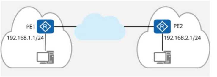
Options:
- A. Configuring NQA on PE1 and PE2, with the destination address being the IP address of each other.
- B. On PE1 and PE2, checking whether the ARP table contains the ARP entry of the peer network segment.
- C. On PE1, using 192.168.1.1 as the source address to ping 192.168.2.1.
- D. On PE1 and PE2, checking whether there are routes to each other’s network segment in the routing tables.
Answer:
A, C, D
Explanation:
Comprehensive and Detailed In-Depth
1. Understanding the Network Setup
PE1 (Provider Edge 1) is the gateway for network 192.168.1.1/24.
PE2 (Provider Edge 2) is the gateway for network 192.168.2.1/24.
A cloud-based backbone connects PE1 and PE2.
To verify end-to-end communication, engineers need to check reachability between PE1 and PE2.
2. Evaluating Each Answer Option
Option A: "Configuring NQA on PE1 and PE2, with the destination address being the IP address of
each other."
✅
Correct.
NQA (Network Quality Analysis) is a network testing tool that allows connectivity testing between
two devices.
Configuring NQA between PE1 and PE2 will verify end-to-end reachability.
Option B: "On PE1 and PE2, checking whether the ARP table contains the ARP entry of the peer
network segment."
❌
Incorrect.
ARP (Address Resolution Protocol) is only used for resolving MAC addresses within the same
broadcast domain.
Since PE1 and PE2 are in different network segments (separated by a routed network), they will not
have ARP entries for each other.
Instead, routing entries should be checked, not ARP.
Option C: "On PE1, using 192.168.1.1 as the source address to ping 192.168.2.1."
✅
Correct.
A simple ping test using the source address of PE1 (192.168.1.1) to reach PE2 (192.168.2.1) will verify
whether routing between the two locations is functional.
Option D: "On PE1 and PE2, checking whether there are routes to each other’s network segment in
the routing tables."
✅
Correct.
If routing is not configured correctly, PE1 and PE2 will not know how to reach each other.
Checking the routing table ensures that both PEs have the correct next-hop information.
Final Answer:
✅
A, C, and D are correct.
HCIP-Datacom-Advanced Routing & Switching Technology Reference:
Using NQA for Network Connectivity Testing
Verifying Routing Table Entries for Inter-Network Communication
Understanding ARP and Its Limitations in Routed Networks
Question 2
The figure shows the logical network architecture of a migration project. The purpose of the
migration is to add network device R4 between R2 and R3.
OSPF runs between network devices.
After the physical network is connected, a network engineer incorrectly imports the backup
configuration of R3 to R4 during the migration.
Given this, which of the following statements are true?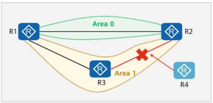
Options:
- A. The OSPF neighbor relationship between R1 and R2 is not affected.
- B. An OSPF neighbor relationship can be established between R2 and R4.
- C. An OSPF neighbor relationship can be established between R3 and R4.
- D. An OSPF neighbor relationship can be established between R1 and R3.
Answer:
AC
Explanation:
Comprehensive and Detailed In-Depth
1. Understanding OSPF Neighbor Relationships
OSPF (Open Shortest Path First) forms neighbor relationships based on these key conditions:
Routers must be in the same OSPF area.
The subnet mask and network type must match.
The Hello/Dead timers must match.
Authentication (if enabled) must match.
2. Analyzing the Given Scenario
R1 and R2 are in Area 0 (Backbone Area).
R3 and R4 are in Area 1 (Non-Backbone Area).
R4 was configured incorrectly using R3’s backup configuration, which could cause issues.
3. Evaluating Each Answer Option
Option A: "The OSPF neighbor relationship between R1 and R2 is not affected."
Correct.
R1 and R2 are both in Area 0 and their configuration was not changed.
Since R4 was added only between R2 and R3, it does not impact R1 and R2.
✅
A is correct.
Option B: "An OSPF neighbor relationship can be established between R2 and R4."
Incorrect.
R2 is in Area 0, but R4 is incorrectly configured using R3’s backup, which likely placed it in Area 1.
OSPF neighbors cannot form across different areas unless an Area Border Router (ABR) is properly
configured.
Since there is no indication of an ABR setup, the adjacency will fail.
❌
B is incorrect.
Option C: "An OSPF neighbor relationship can be established between R3 and R4."
Correct.
R3 and R4 are both in Area 1, and R4's backup configuration comes from R3, meaning they likely have
identical settings.
Since they share the same area and are directly connected, an OSPF adjacency is possible.
✅
C is correct.
Option D: "An OSPF neighbor relationship can be established between R1 and R3."
Incorrect.
R1 is in Area 0, and R3 is in Area 1.
OSPF does not form neighbor relationships between different areas unless configured as an ABR,
which is not mentioned.
❌
D is incorrect.
Final Answer:
✅
A and C are correct.
HCIP-Datacom-Advanced Routing & Switching Technology Reference:
OSPF Neighbor Formation and Area Design Principles
Troubleshooting OSPF Area Mismatches and Configuration Issues
OSPF Backbone Area (Area 0) and Inter-Area Communication
Question 3
On the network shown in the figure, PC1 and PC2 are connected to the same switch (SW1) and
belong to the same VLAN.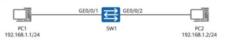
Which of the following are possible causes of a communication failure between PC1 and PC2?
Options:
- A. SW1’s GE0/0/2 is shut down.
- B. The link of SW1’s GE0/0/1 is faulty.
- C. Incorrect static ARP entries are configured on the hosts.
- D. Port isolation is configured on SW1.
Answer:
A, B, C, D
Explanation:
Comprehensive and Detailed In-Depth
1. Understanding the Network Setup
PC1 (192.168.1.1/24) and PC2 (192.168.1.2/24) are connected to SW1.
Both PCs are in the same VLAN, meaning communication should work without routing.
If there is a communication failure, it could be due to physical, VLAN, ARP, or port security issues.
2. Evaluating Each Answer Option
Option A: "SW1’s GE0/0/2 is shut down."
Correct.
If GE0/0/2 is shut down, PC2 cannot send or receive traffic, causing communication failure.
Even if PC1 is working, PC2 will be unreachable.
✅
A is a valid cause.
Option B: "The link of SW1’s GE0/0/1 is faulty."
Correct.
If GE0/0/1 has a faulty link, PC1 cannot communicate with PC2, causing failure.
Even if PC2 is working, PC1 will be unreachable.
✅
B is a valid cause.
Option C: "Incorrect static ARP entries are configured on the hosts."
Correct.
If static ARP entries are incorrectly configured, PCs will map the wrong MAC addresses to IPs.
This will result in packet delivery failures, even if the physical network is working.
✅
C is a valid cause.
Option D: "Port isolation is configured on SW1."
Correct.
Port isolation (or private VLAN) prevents direct communication between specific ports.
If port isolation is enabled on GE0/0/1 and GE0/0/2, PC1 and PC2 will be unable to reach each other.
✅
D is a valid cause.
Final Answer:
✅
A, B, C, and D are correct.
HCIP-Datacom-Advanced Routing & Switching Technology Reference:
Troubleshooting VLAN and Layer 2 Communication Issues
Impact of Port Isolation and Private VLANs on Communication
Static ARP Entry Configuration and Its Effects on Network Connectivity
Question 4
A network engineer provides a troubleshooting report after rectifying a fault. The actual network is
simplified into the one shown in the figure, where:
R1 and R2 both have OSPF enabled.
R1 and R2 function as the gateways for PC1 and PC2, respectively.
Given this, which of the following statements are true?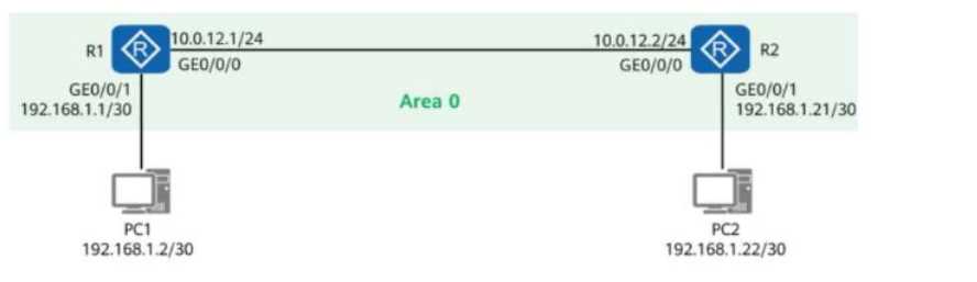
Options:
- A. R1 can ping 192.168.1.22.
- B. R1 can ping 192.168.1.21.
- C. R2 can ping 192.168.1.2.
- D. PC1 and PC2 cannot ping each other.
Answer:
A, B, C
Explanation:
Comprehensive and Detailed In-Depth
1. Understanding the Network Topology
R1 and R2 are OSPF-enabled routers connected via the 10.0.12.0/24 subnet (Area 0).
PC1 (192.168.1.2/30) is connected to R1 via GE0/0/1.
PC2 (192.168.1.22/30) is connected to R2 via GE0/0/1.
OSPF ensures that R1 and R2 know about each other's directly connected networks.
2. Analyzing Connectivity
Can R1 ping 192.168.1.22 (PC2)?
Yes, if routing is properly configured.
OSPF ensures that R1 learns about 192.168.1.22 from R2.
Since R1 has a route to 192.168.1.22 via R2, it can ping PC2 successfully.
✅
Option A is correct.
Can R1 ping 192.168.1.21 (R2's interface)?
Yes, since R1 and R2 are OSPF neighbors.
R1 learns 192.168.1.21 via OSPF and can reach it directly.
✅
Option B is correct.
Can R2 ping 192.168.1.2 (PC1)?
Yes, since OSPF ensures that R2 learns about 192.168.1.2 from R1.
Since R2 has a route to 192.168.1.2 via R1, it can ping PC1 successfully.
✅
Option C is correct.
Can PC1 and PC2 ping each other?
Yes, if default gateways and routing are configured correctly.
If R1 and R2 can ping each other and forward packets, PC1 and PC2 should be able to communicate.
❌
Option D is incorrect because PC1 and PC2 should be able to ping each other.
Final Answer:
✅
A, B, and C are correct.
HCIP-Datacom-Advanced Routing & Switching Technology Reference:
OSPF Inter-Router Communication and Route Advertisement
Default Gateway and Routing in Multi-Router Networks
Troubleshooting End-to-End Connectivity in Routed Networks
Question 5
On the OSPF network shown in the figure, R1 and R2 use OSPF to communicate with each other
through Loopback0. In addition:
MPLS LDP is enabled on R1 and R2.
The LDP transport address is the IP address of Loopback0.
A network engineer finds that an LDP session cannot be established between R1 and R2 and runs
diagnostic commands (shown in the figure) to locate the fault.
Given this, which of the following are possible causes of the fault?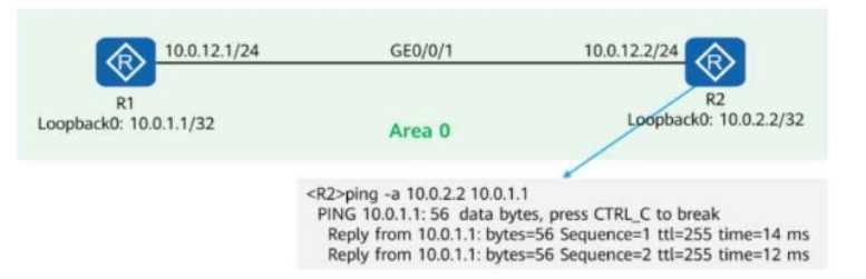
Options:
- A. R1’s GE0/0/1 rejects packets with the destination IP address 10.0.2.2.
- B. MPLS LDP is not enabled on R2’s GE0/0/1.
- C. R2’s GE0/0/1 rejects packets with TCP destination port 646.
- D. R1’s GE0/0/1 rejects packets with UDP destination port 646.
Answer:
BC
Explanation:
Comprehensive and Detailed In-Depth
1. Understanding MPLS LDP (Label Distribution Protocol)
LDP (Label Distribution Protocol) runs over TCP port 646.
LDP uses the transport address (Loopback0 in this case) to establish TCP sessions between neighbors.
For an LDP session to be established, both routers must:
Enable LDP on the interface (GE0/0/1).
Allow TCP traffic on port 646 (used for LDP adjacency formation).
2. Analyzing the Issue and Possible Causes
The figure shows a successful ping from R2 to R1’s Loopback0 (10.0.1.1/32).
This means basic IP connectivity between R1 and R2 is working.
OSPF is properly advertising Loopback0 addresses between the routers.
The problem must be related to LDP itself, not general IP reachability.
3. Evaluating Each Answer Option
Option A: "R1’s GE0/0/1 rejects packets with the destination IP address 10.0.2.2."
Incorrect.
The ping test in the figure shows successful replies from 10.0.1.1 to 10.0.2.2, meaning packets to
10.0.2.2 are not being rejected.
This is NOT the cause of the LDP failure.
Option B: "MPLS LDP is not enabled on R2’s GE0/0/1."
Correct.
If LDP is not enabled on R2’s GE0/0/1, then R1 and R2 cannot form an LDP session.
MPLS LDP must be enabled on both interfaces for label exchange.
This is a valid cause of the issue.
Option C: "R2’s GE0/0/1 rejects packets with TCP destination port 646."
Correct.
LDP operates over TCP port 646, so if R2’s GE0/0/1 has a firewall or ACL blocking TCP port 646, then
LDP will fail.
Blocking TCP 646 on R2’s interface would prevent the session from establishing.
This is another valid cause of the issue.
Option D: "R1’s GE0/0/1 rejects packets with UDP destination port 646."
Incorrect.
LDP does not use UDP; it uses TCP port 646.
This is not a valid cause of the issue.
Final Answer:
✅
B and C are correct.
HCIP-Datacom-Advanced Routing & Switching Technology Reference:
MPLS LDP Session Establishment and TCP 646 Dependency
How OSPF Advertises Loopback0 for LDP Transport
Common LDP Debugging Techniques and ACL Issues
Question 6
In the figure, a network administrator configures a static LSP to implement MPLS data forwarding.
The lower part of the topology shows the packet header information obtained from a device.
Which of the following statements are true?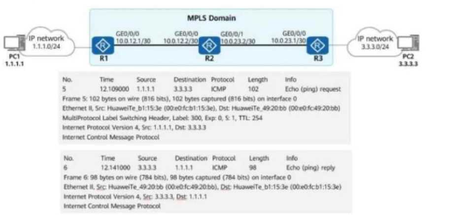
Options:
- A. If the device is R3, R3 forwards the packet from PC1 to PC2 over an IP route.
- B. Packets from PC1 to PC2 are forwarded based on MPLS labels in the MPLS domain.
- C. Packets from PC2 to PC1 are forwarded based on the IP packet header in the MPLS domain.
- D. PC1 pings PC2.
Answer:
BD
Explanation:
Comprehensive and Detailed In-Depth
1. Understanding the MPLS Data Flow in the Figure
PC1 (1.1.1.1) sends a ping to PC2 (3.3.3.3).
The MPLS domain includes R1, R2, and R3.
R1 pushes an MPLS label onto the packet (Label: 300).
Packets from PC1 to PC2 are label-switched (MPLS forwarding).
Packets from PC2 to PC1 do not carry an MPLS label (IP forwarding).
2. Evaluating Each Answer Option
Option A: "If the device is R3, R3 forwards the packet from PC1 to PC2 over an IP route."
Incorrect.
The packet carries an MPLS label (Label 300) when entering the MPLS domain.
This means that R3 forwards the packet using MPLS, not a standard IP route.
If R3 were using an IP route, there would be no MPLS label in the packet.
Option B: "Packets from PC1 to PC2 are forwarded based on MPLS labels in the MPLS domain."
Correct.
The packet capture shows an MPLS label (Label 300), proving that PC1’s traffic is being forwarded
using MPLS switching inside the MPLS domain.
This confirms that MPLS is being used for forwarding in one direction (PC1 → PC2).
Option C: "Packets from PC2 to PC1 are forwarded based on the IP packet header in the MPLS
domain."
Correct in concept but incorrect in context.
The packet capture shows that the return traffic (PC2 → PC1) does not have an MPLS label.
However, the phrase "in the MPLS domain" makes this statement misleading, as R3 is forwarding
based on pure IP routing, not MPLS forwarding.
Option D: "PC1 pings PC2."
Correct.
The packet capture clearly shows ICMP Echo Request (ping) from PC1 (1.1.1.1) to PC2 (3.3.3.3) and
an ICMP Echo Reply from PC2.
This confirms that PC1 is pinging PC2 successfully.
Final Answer:
✅
B and D are correct.
HCIP-Datacom-Advanced Routing & Switching Technology Reference:
MPLS Label Forwarding and Static LSPs
MPLS vs. IP Routing in Different Traffic Flows
Packet Header Analysis in MPLS Networks
Question 7
As shown in the figure, R1 to R4 are four routers in AS123. They all run OSPF to implement route
reachability within the AS.
Network segments 10.1.1.0/24 and 10.4.4.0/24 are not advertised into OSPF.
R1 and R4 establish an IBGP peer relationship using Loopback0 and advertise network segments
10.1.1.0/24 and 10.4.4.0/24 into BGP.
Which of the following methods can be used to implement communication between PC1 and PC2?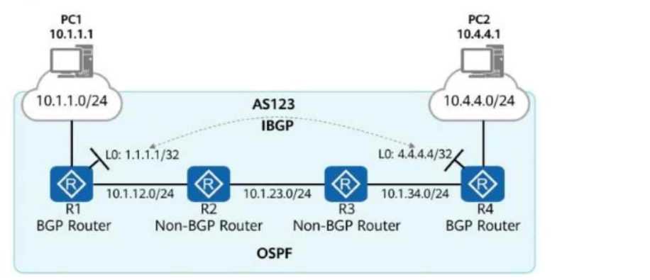
Options:
- A. Deploy policy-based routing on R1 and specify R2 as the next hop for traffic from PC1 to PC2.
- B. Deploy MPLS and LDP on R1 to R4 and establish LSPs for routes 1.1.1.1/32 and 4.4.4.4/32.
- C. Run BGP on R2 and R3, and establish full-mesh IBGP connections in AS 123.
- D. On R1 and R4, import routes 10.1.1.0/24 and 10.4.4.0/24 into OSPF.
Answer:
CD
Explanation:
Comprehensive and Detailed In-Depth
1. Understanding the Routing Issue
R1 and R4 are BGP routers and have an IBGP connection.
R2 and R3 are OSPF-only routers (they do not run BGP).
Networks 10.1.1.0/24 and 10.4.4.0/24 are advertised into BGP but not OSPF.
PC1 (10.1.1.1) and PC2 (10.4.4.1) need communication, but their networks are not known to OSPF
routers R2 and R3.
To fix this, we need a method that ensures R2 and R3 learn the routes for 10.1.1.0/24 and
10.4.4.0/24.
2. Evaluating Each Answer Option
Option A: "Deploy policy-based routing on R1 and specify R2 as the next hop for traffic from PC1 to
PC2."
Incorrect.
Policy-Based Routing (PBR) does not solve the issue of missing routes in OSPF.
Even if R1 forwards traffic to R2, R2 does not know how to reach 10.4.4.0/24, causing packet drops.
A proper routing protocol solution is required instead of PBR.
Option B: "Deploy MPLS and LDP on R1 to R4 and establish LSPs for routes 1.1.1.1/32 and
4.4.4.4/32."
Incorrect.
MPLS requires label-switched paths (LSPs) but does not distribute routing information itself.
The real problem is that R2 and R3 do not have routing entries for 10.1.1.0/24 and 10.4.4.0/24.
MPLS does not fix the missing route advertisement issue.
Option C: "Run BGP on R2 and R3, and establish full-mesh IBGP connections in AS 123."
Correct.
If R2 and R3 run BGP, they can form IBGP sessions with R1 and R4 and learn routes 10.1.1.0/24 and
10.4.4.0/24 via BGP.
R2 and R3 would then be able to forward traffic correctly between PC1 and PC2.
This is a valid method to fix the issue.
Option D: "On R1 and R4, import routes 10.1.1.0/24 and 10.4.4.0/24 into OSPF."
Correct.
By redistributing BGP routes into OSPF, R1 and R4 can ensure that R2 and R3 learn the missing
networks (10.1.1.0/24 and 10.4.4.0/24) via OSPF.
This allows full reachability without running BGP on R2 and R3.
This is another valid method to fix the issue.
Final Answer:
✅
C and D are correct.
HCIP-Datacom-Advanced Routing & Switching Technology Reference:
BGP and OSPF Route Redistribution
IBGP Full-Mesh Requirement and Route Propagation
How Policy-Based Routing Works and Its Limitations
Question 8
An administrator runs the display mpls lsp command to view LSPs on a device. The command output
is shown in the figure.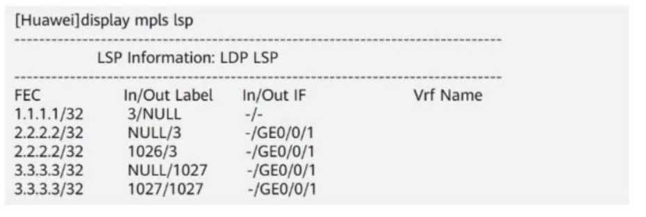
Which of the following statements is true?
Options:
- A. Before forwarding a packet destined for 2.2.2.2, the device adds label 3 to the packet.
- B. Before forwarding a packet destined for 1.1.1.1, the device adds label 3 to the packet.
- C. Before forwarding a packet destined for any IP address, the device removes labels from the packet.
- D. Before forwarding a packet destined for 3.3.3.3, the device adds label 1027 to the packet.
Answer:
D
Explanation:
Comprehensive and Detailed In-Depth
1. Understanding MPLS Label Forwarding Information
The output of the display mpls lsp command shows the Label Forwarding Information Base (LFIB)
used by the router to forward MPLS packets.
Each entry consists of:
FEC (Forwarding Equivalence Class): The destination IP prefix.
In Label / Out Label: Incoming label (received) and outgoing label (sent).
In IF / Out IF: Incoming and outgoing interfaces.
2. Analyzing the Given LSP Table
Outgoing
FEC (Destination IP) In Label Out Label
Interface
1.1.1.1/32
NULL
-
2.2.2.2/32
NULL 3
GE0/0/1
2.2.2.2/32
1026 3
GE0/0/1
3.3.3.3/32
NULL 1027
GE0/0/1
3.3.3.3/32
1027 1027
GE0/0/1
Key Observations:
NULL means the label is removed (Penultimate Hop Popping - PHP).
Label 3 is the implicit null label, meaning the label is removed before sending to the next router.
For destination 3.3.3.3, the router adds label 1027 before forwarding it to GE0/0/1.
3. Evaluating Each Answer Option
Option A: "Before forwarding a packet destined for 2.2.2.2, the device adds label 3 to the packet." →
Incorrect.
The output shows that packets destined for 2.2.2.2 have the NULL (label 3) entry, which means the
label is removed before forwarding, not added.
Option B: "Before forwarding a packet destined for 1.1.1.1, the device adds label 3 to the packet." →
Incorrect.
The entry 1.1.1.1 → 3/NULL means the label is removed (PHP), so the device does not add label 3.
Option C: "Before forwarding a packet destined for any IP address, the device removes labels from
the packet." → Incorrect.
The device removes labels only for some destinations (e.g., 1.1.1.1 and 2.2.2.2), but it adds label
1027 for 3.3.3.3.
Not all IPs have their labels removed.
Option D: "Before forwarding a packet destined for 3.3.3.3, the device adds label 1027 to the packet."
→ Correct.
The entry 3.3.3.3 → NULL/1027 means that the router adds label 1027 before forwarding packets to
GE0/0/1.
Final Answer:
Answer : D (Before forwarding a packet destined for 3.3.3.3, the device adds label 1027 to the
packet).
Explanation:
HCIP-Datacom-Advanced Routing & Switching Technology Reference:
Understanding MPLS LDP (Label Distribution Protocol) and LFIB
Implicit Null (Label 3) and Penultimate Hop Popping (PHP)
MPLS Label Swapping and Forwarding Process
Question 9
In the figure, packets are forwarded based on MPLS on the network.
When PE2 receives a packet from P2, what is the label value carried in the packet?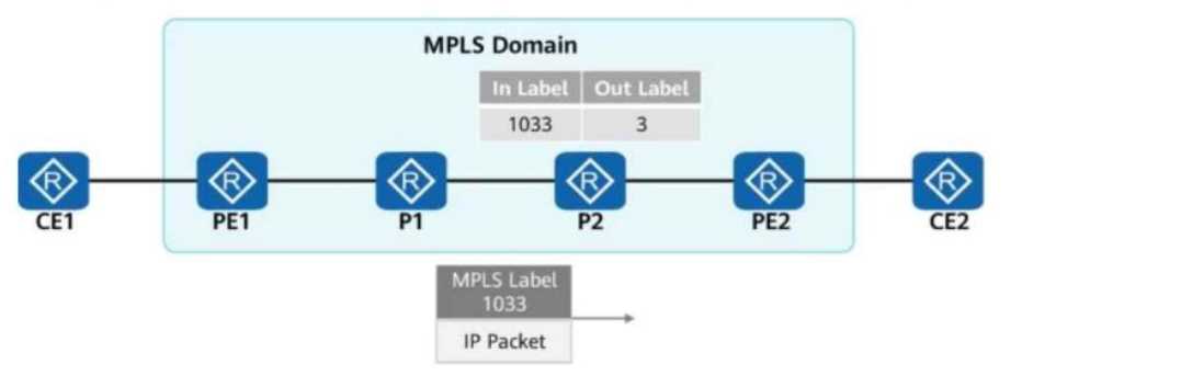
Options:
- A. The label value is 3.
- B. There is no label.
- C. The label value is 1033.
- D. The label values are 3 and 1033.
Answer:
B
Explanation:
Comprehensive and Detailed In-Depth
1. Understanding MPLS Label Switching
MPLS (Multiprotocol Label Switching) operates by adding labels to packets to enable fast switching
across an MPLS domain.
Labels are swapped at each router (LSR - Label Switch Router) based on the LFIB (Label Forwarding
Information Base).
When an MPLS packet reaches a router, it checks the incoming label and swaps it with an outgoing
label as per its label forwarding table.
The label value "3" is the implicit null label, which is used for PHP (Penultimate Hop Popping).
2. Analyzing the MPLS Label Flow in the Figure
At PE1: The packet enters the MPLS domain and is labeled with 1033.
At P1: P1 forwards the packet based on label 1033.
At P2:
P2 receives label 1033 and swaps it with label 3 (as per the figure).
Label 3 (implicit null) means that the label is removed before reaching PE2 (PHP - Penultimate Hop
Popping).
This ensures that PE2 receives a pure IP packet without an MPLS label.
3. Evaluating Each Answer Option
Option A: "The label value is 3." → Incorrect.
Label 3 (implicit null) is not actually sent to PE2.
Instead, P2 removes the label before sending the packet to PE2.
Option B: "There is no label." → Correct.
Since P2 performs PHP (Penultimate Hop Popping), the label is removed, and PE2 receives only an IP
packet.
Option C: "The label value is 1033." → Incorrect.
Label 1033 was used earlier in the MPLS path but was swapped out before reaching PE2.
Option D: "The label values are 3 and 1033." → Incorrect.
Only one label is present at a time.
Label 1033 was swapped for label 3, but label 3 was removed before reaching PE2.
Final Answe r :
Answe r: B (There is no label).
HCIP-Datacom-Advanced Routing & Switching Technology Reference:
MPLS Label Forwarding Mechanism
Penultimate Hop Popping (PHP) and Implicit Null Label (3)
MPLS Label Swapping and Label Forwarding Table (LFIB)
Question 10
On the network shown in the figure, the network administrator configures the DHCP snooping trust
function on the switch.
GE0/0/2 is a trusted interface (connected to the DHCP Server).
GE0/0/3 is an untrusted interface (potential attacker).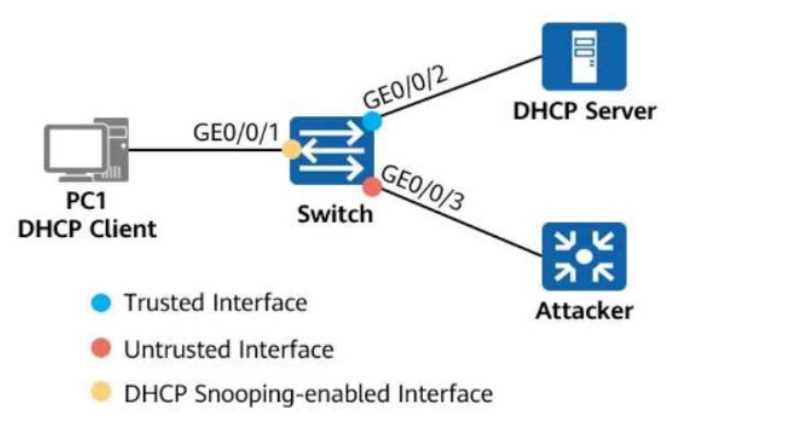
Which of the following statements are true about the two interfaces?
Options:
- A. When receiving a DHCP response packet on GE0/0/2, the switch forwards the packet through GE0/0/1.
- B. When receiving a DHCP request packet on GE0/0/2, the switch forwards the packet through GE0/0/3.
- C. When receiving a DHCP response packet on GE0/0/3, the switch forwards the packet through GE0/0/1.
- D. When receiving a DHCP request packet on GE0/0/3, the switch forwards the packet through GE0/0/2.
Answer:
AD
Explanation:
Comprehensive and Detailed In-Depth
1. Understanding DHCP Snooping
DHCP Snooping is a security feature that filters untrusted DHCP messages to prevent attacks such as:
Rogue DHCP servers distributing incorrect IP addresses.
DHCP starvation attacks.
In DHCP Snooping, switch ports are classified as:
Trusted Interfaces: Allow both DHCP requests and DHCP responses to pass through.
Untrusted Interfaces: Allow only DHCP requests but drop DHCP responses (to prevent rogue DHCP
servers).
2. Analyzing Each Answer Option
Option A: "When receiving a DHCP response packet on GE0/0/2, the switch forwards the packet
through GE0/0/1."
Correct.
GE0/0/2 is a trusted interface (connected to the DHCP server).
DHCP responses (ACK, NAK, OFFER) come from the DHCP Server.
Since DHCP responses are allowed on trusted interfaces, the switch forwards them to the client (PC1)
via GE0/0/1.
Option B: "When receiving a DHCP request packet on GE0/0/2, the switch forwards the packet
through GE0/0/3."
Incorrect.
DHCP requests originate from clients (PC1, attackers, etc.), not from the DHCP server.
The DHCP request should be forwarded to the DHCP server via a trusted interface (not GE0/0/3,
which is untrusted).
Option C: "When receiving a DHCP response packet on GE0/0/3, the switch forwards the packet
through GE0/0/1."
Incorrect.
GE0/0/3 is an untrusted interface (connected to the attacker).
DHCP responses (ACK, OFFER) from untrusted interfaces are dropped to prevent rogue DHCP attacks.
The switch will not forward the packet.
Option D: "When receiving a DHCP request packet on GE0/0/3, the switch forwards the packet
through GE0/0/2."
Correct.
DHCP requests originate from clients (PC1 or attacker).
Since DHCP requests are allowed on untrusted interfaces, the switch forwards them to the DHCP
server via the trusted interface (GE0/0/2).
Final Answer:
✅
A and D are correct.
HCIP-Datacom-Advanced Routing & Switching Technology Reference:
DHCP Snooping and Port Trust Classification
How Trusted and Untrusted Ports Handle DHCP Packets
Preventing Rogue DHCP Servers Using DHCP Snooping
Question 11
DRAG DROP
When configuring port security on a switch, the administrator also enables static MAC address
flapping detection. If static MAC address flapping occurs, the switch takes the configured action to
protect the interface.
Match the names of interface security protection actions with corresponding operations.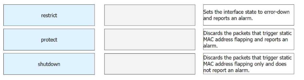
Answer:
None
Explanation:
Restrict → Discards the packets that trigger static MAC address flapping and reports an alarm.
Protect → Discards the packets that trigger static MAC address flapping only and does not report an
alarm.
Shutdown → Sets the interface state to error-down and reports an alarm.
Comprehensive and Detailed In-Depth
1. Understanding Port Security Modes
Port security is used to control access on a switch port based on MAC addresses. If a MAC address
violation occurs (e.g., static MAC address flapping), the switch can take different actions based on the
configured security mode.
Security Mode Description
Restrict
Drops the violating packets and logs the violation by generating an alarm.
Protect
Drops the violating packets but does not generate an alarm.
Places the interface into error-disabled (error-down) state and logs an
Shutdown
alarm.
2. Matching Each Security Mode with Its Operation
Protect Mode:
The switch drops the packets from the unauthorized MAC address.
No alarm is generated or logged.
Correct Mapping: "Discards the packets that trigger static MAC address flapping only and does not
report an alarm."
Restrict Mode:
The switch drops the packets from the unauthorized MAC address.
An alarm is generated and logged in the system.
Correct Mapping: "Discards the packets that trigger static MAC address flapping and reports an
alarm."
Shutdown Mode:
The switch shuts down the interface by placing it into the error-down state.
An alarm is generated and logged.
Correct Mapping: "Sets the interface state to error-down and reports an alarm."
Question 12
On the OSPFv3 network shown in the figure, the LSDB (Link-State Database) of R2 contains ______
Router-LSAs. (Enter only digits.)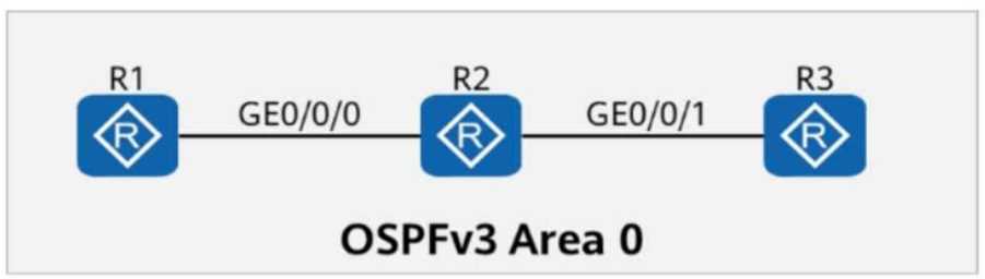
Answer:
3
Explanation:
1. Understanding Router-LSAs in OSPFv3
Router-LSA (Type 1 LSA) is generated by every OSPFv3 router to describe its own links and connected
networks within the same area.
Each router in an OSPF area generates exactly one Router-LSA to advertise its own topology
information.
Router-LSAs are flooded throughout the area but do not cross area boundaries.
2. Analyzing the Given OSPFv3 Network
The topology consists of three routers: R1, R2, and R3, all connected in OSPFv3 Area 0.
Since all three routers participate in OSPFv3, each router generates its own Router-LSA (Type 1 LSA).
R2, as an OSPF router, will have its own Router-LSA and also receive the Router-LSAs from R1 and R3.
3. Counting the Number of Router-LSAs in R2’s LSDB
R1 generates 1 Router-LSA (for itself).
R2 generates 1 Router-LSA (for itself).
R3 generates 1 Router-LSA (for itself).
Total Router-LSAs in R2’s LSDB = 3 (one from each router).
Final Answer:
Answe r: 3
Explanation:
HCIP-Datacom-Advanced Routing & Switching Technology Reference:
OSPFv3 LSA Types and Their Roles
Understanding Router-LSA (Type 1) and Its Function in LSDB
Question 13
On the OSPFv3 network shown in the figure, OSPFv3 is enabled on the interfaces connecting R1, R2,
and R3. The router ID of each router is 10.0.X.X, where X is the number of the router.
If you check detailed information about an LSA on R3, the command output shows that R1 and R2 are
DRs on the network.
Options:
- A. TRUE
- B. FALSE
Answer:
B
Explanation:
Comprehensive and Detailed In-Depth
1. Understanding OSPFv3 and DR/BDR Election
In OSPFv3, on broadcast and non-broadcast networks, routers elect a Designated Router (DR) and a
Backup Designated Router (BDR) to reduce LSA flooding.
The DR is responsible for generating Network LSAs (Type 2 LSAs) for the subnet.
The BDR takes over if the DR fails.
Other routers (DROther) only form adjacencies with the DR and BDR but still receive LSAs.
2. Understanding the LSA Output in the Figure
The LSA shown in the figure is a Type 1 (Router LSA).
The originating router is R2 (Router ID: 10.0.2.2).
The LSA lists two "Transit Network" links connected to R2.
The Neighbor Router IDs listed are 10.0.1.1 (R1) and 10.0.2.2 (R2).
3. Why the Statement is FALSE
A transit network (broadcast network) should have only ONE DR.
R1 and R2 both being DRs is incorrect, as only one DR per subnet should exist.
The presence of two "Transit Network" entries in the LSA suggests that there are two separate OSPF
broadcast networks, each with its own DR.
This means R1 and R2 are each DRs on separate networks, but not both DRs on the same network.
Final Answer:
Answe r: B (FALSE)
Explanation:
HCIP-Datacom-Advanced Routing & Switching Technology Reference:
OSPFv3 DR/BDR Election Process
OSPFv3 LSA Types and Their Roles
OSPFv3 Network Topology and LSA Interpretation
Question 14
The figure shows information about an LSP (Link-State PDU) generated by an IS-IS router.
From the LSP, you can infer that the router is not the DIS (Designated Intermediate System) of the
local link.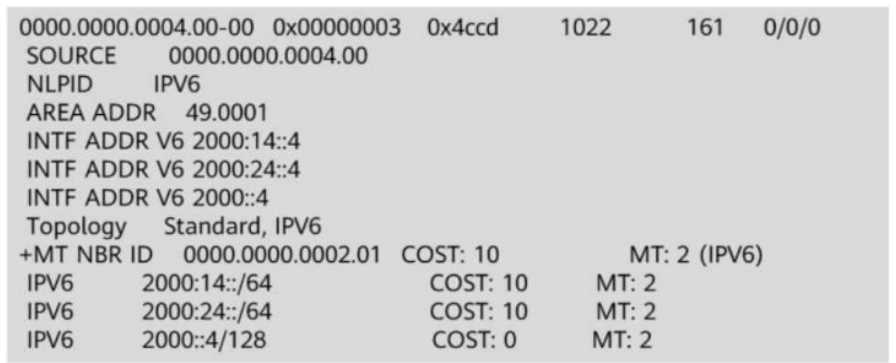
Options:
- A. TRUE
- B. FALSE
Answer:
A
Explanation:
Comprehensive and Detailed In-Depth
1. Understanding the DIS (Designated Intermediate System) in IS-IS
In IS-IS, the DIS (Designated Intermediate System) is similar to the DR (Designated Router) in OSPF.
Unlike OSPF, IS-IS does not use an election based on priority; instead, the router with the highest
priority becomes the DIS.
If there is a tie in priority, the router with the highest MAC address on the interface becomes the DIS.
The DIS is responsible for generating additional LSPs (pseudonode LSPs) for the link and
synchronizing the database between routers.
2. How to Identify If the Router Is the DIS from the LSP
In the given LSP output, there are NO pseudonode LSPs (LSPs ending with .01).
The DIS is responsible for creating pseudonode LSPs, which represent a multi-access network in the
IS-IS topology.
If the router were the DIS, it would generate both its own LSP (ending in .00) and a pseudonode LSP
(ending in .01).
Since we only see an LSP ending in .00, this confirms that the router is NOT the DIS.
3. Evaluating the Answer Choices
Option A (TRUE) – Correct:
Since no pseudonode LSP is present, the router is not the DIS.
This confirms that the statement is TRUE.
Option B (FALSE) – Incorrect:
If the router were the DIS, it would generate pseudonode LSPs, but they are missing from the output.
Therefore, the statement is NOT false.
Final Answer:
Answe r: A (TRUE)
Explanation:
HCIP-Datacom-Advanced Routing & Switching Technology Reference:
IS-IS Designated Intermediate System (DIS) Selection Process
Pseudonode LSP Generation in Multi-Access Networks
IS-IS LSP Structure and Identification of DIS
Question 15
On the OSPFv3 network shown in the figure, area 1 is a common are
a. R2 generates an Inter-Area-Prefix-LSA to describe the routes of a network segment in the area.
Such an LSA exists in both area 0 and area 1.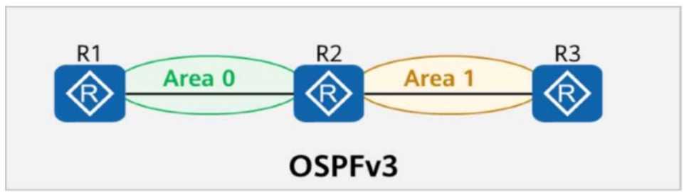
- A. TRUE
- B. FALSE
Answer:
A
Explanation:
Comprehensive and Detailed In-Depth
To determine whether the statement is true or false, we need to analyze the OSPFv3 topology, the
role of area types, and the behavior of Inter-Area-Prefix-LSAs. Let’s break it down step by step:
Understanding the OSPFv3 Topology and Area Types:
The figure shows three routers (R1, R2, and R3) connected in an OSPFv3 network. R1 and R2 are in
Area 0 (the backbone area), while R2 and R3 are in Area 1 (a common area, also known as a standard
or regular area).
R2 is an Area Border Router (ABR) because it connects Area 0 and Area 1. ABRs are responsible for
summarizing and advertising routes between areas.
What is a Common Area in OSPFv3?:
A "common area" in OSPFv3 refers to a standard or regular OSPF area, as opposed to special areas
like Stub, Totally Stubby, Not-So-Stubby Area (NSSA), or Totally NSSA. Common areas allow all types
of LSAs, including inter-area, intra-area, and external LSAs, to be flooded within the area, except for
restrictions in special area types.
Since Area 1 is described as a "common area," it behaves like a standard OSPF area, allowing the full
exchange of LSAs, including Inter-Area-Prefix-LSAs.
Role of Inter-Area-Prefix-LSA (Type 3 LSA in OSPFv3):
Inter-Area-Prefix-LSAs (Type 3 LSAs in OSPFv3) are used by ABRs to advertise prefixes from one area
to another. These LSAs are critical for inter-area routing, allowing routers in one area to learn about
networks in other areas.
In this case, R2, as an ABR, generates Inter-Area-Prefix-LSAs to describe routes (network segments)
in Area 1 and advertises them into Area 0. Conversely, R2 also receives Inter-Area-Prefix-LSAs from
Area 0 (via R1) and advertises them into Area 1.
Does the Inter-Area-Prefix-LSA Exist in Both Area 0 and Area 1?:
Yes, Inter-Area-Prefix-LSAs exist in both areas because R2, as an ABR, floods these LSAs into both
Area 0 and Area 1. Specifically:
R2 generates Inter-Area-Prefix-LSAs for network segments in Area 1 and advertises them into Area 0,
where R1 (in Area 0) can receive and process them.
Similarly, R2 receives Inter-Area-Prefix-LSAs for network segments in Area 0 (from R1) and advertises
them into Area 1, where R3 (in Area 1) can receive and process them.
Since Area 1 is a common area (not a stub or NSSA), it allows Inter-Area-Prefix-LSAs to be flooded
within the area, ensuring that routers like R3 can learn about routes in Area 0, and routers like R1 can
learn about routes in Area 1.
Verifying the Statement:
The statement claims that R2 generates an Inter-Area-Prefix-LSA to describe the routes of a network
segment in Area 1, and such an LSA exists in both Area 0 and Area 1. This is accurate because:
R2, as an ABR, generates Inter-Area-Prefix-LSAs for Area 1’s network segments and floods them into
Area 0.
R2 also receives and floods Inter-Area-Prefix-LSAs from Area 0 into Area 1.
Therefore, Inter-Area-Prefix-LSAs describing routes in Area 1 exist in both Area 0 and Area 1, making
the statement true.
Conclusion:
The statement is true because Inter-Area-Prefix-LSAs generated by R2 for Area 1’s network segments
are flooded into both Area 0 and Area 1, and Area 1, being a common area, allows these LSAs to exist
within it.
Reference to HCIP-Datacom-Advanced Routing & Switching Technology Documents:
HCIP-Datacom-Advanced Routing & Switching Technology V1.0, Section on OSPFv3: OSPF Area Types,
Inter-Area Routing, and LSA Types (specifically Inter-Area-Prefix-LSA, Type 3 LSA).
HCIP-Datacom-Advanced Routing & Switching Technology V1.0, Chapter on OSPF Routing Protocols:
ABR Behavior, Common Areas, and LSA Flooding Mechanisms.