dell D-SNC-DY-00 Exam Questions
Questions for the D-SNC-DY-00 were updated on : Feb 20 ,2026
Page 1 out of 3. Viewing questions 1-15 out of 45
Question 1
SIMULATION
Configure a VRF called "VrfGreen" and the static route in it to network 172.16.128.64/28 through
next-hop 10.10.10.1. Set an administrative distance of 213.
Answer:
see the
explanation for all
step by step solution
with all explanation.
Explanation:
Here are the steps to configure the VRF and the static route:
Enter Configuration Mode:
sonic# configure terminal
Create VRF "VrfGreen":
sonic(config)# ip vrf VrfGreen
Configure the Static Route:
sonic(config)# ip route vrf VrfGreen 172.16.128.64/28 10.10.10.1 213
Save Configuration:
sonic# write memory
Comprehensive Detailed Step by Step Explanation with Reference:
Enter Configuration Mode:
Begin by entering the global configuration mode to make changes to the switch configuration.
Create VRF "VrfGreen":
Use the command ip vrf VrfGreen to create a new VRF named "VrfGreen". This command sets up a
new VRF instance which will isolate the routing table for this VRF from the global routing table and
other VRFs.
Configure the Static Route:
Use the command ip route vrf VrfGreen 172.16.128.64/28 10.10.10.1 213 to configure the static
route.
ip route vrf VrfGreen specifies that the route should be added to the "VrfGreen" VRF.
172.16.128.64/28 is the destination network.
10.10.10.1 is the next-hop IP address.
213 is the administrative distance, which in this case is set to a non-default value to influence route
preference.
Save Configuration:
Save the configuration to ensure the changes persist after a reboot using the write memory
command.
Reference:
Dell Technologies Networking - SONiC
Dell Enterprise SONiC Deployment Guide
These steps provide a comprehensive guide to configure a VRF and a static route within that VRF on a
SONiC-based switch, ensuring the specific requirements for routing and administrative distance are
met.
Question 2
SIMULATION
A customer must configure a peer link between two switches in the L2 MC-LAG scenario.
SwitchB has already been configured. Configure the peer link on SwitchA.
Use the following configuration information:
MC-LAG domain 1
VLAN 101
Peer link Port-Channel 100
SwitchA IP: 192.168.1.1/24
SwitchB IP: 192.168.1.2/24
MC-LAG system MAC: 00:00:00:11:11:11
The physical ports to connect the peer switch are Eth 1/5 and Eth 1/6 for each switch.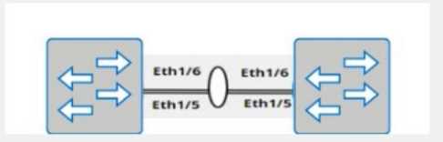

Answer:
see the
explanation for all
step by step solution
with all explanation.
Explanation:
Here are the steps to configure the peer link on SwitchA:
Enter Configuration Mode:
SwitchA# configure terminal
Create VLAN 101:
SwitchA(config)# vlan 101
Create Port-Channel 100:
SwitchA(config)# interface port-channel 100
SwitchA(config-if-po100)# switchport mode trunk
SwitchA(config-if-po100)# switchport trunk allowed vlan 101
SwitchA(config-if-po100)# exit
Assign Physical Interfaces to Port-Channel 100:
SwitchA(config)# interface ethernet 1/5
SwitchA(config-if-eth1/5)# channel-group 100 mode active
SwitchA(config-if-eth1/5)# exit
SwitchA(config)# interface ethernet 1/6
SwitchA(config-if-eth1/6)# channel-group 100 mode active
SwitchA(config-if-eth1/6)# exit
Configure MC-LAG Domain 1:
SwitchA(config)# mclag domain 1
SwitchA(config-mclag-domain)# peer-link port-channel 100
SwitchA(config-mclag-domain)# local-ip 192.168.1.1
SwitchA(config-mclag-domain)# peer-ip 192.168.1.2
SwitchA(config-mclag-domain)# system-mac 00:00:00:11:11:11
SwitchA(config-mclag-domain)# exit
Save Configuration:
SwitchA# write memory
Comprehensive Detailed Step by Step Explanation with Reference:
Enter Configuration Mode:
Begin by entering the global configuration mode to make changes to the switch configuration.
Create VLAN 101:
Create VLAN 101 to be used for the MC-LAG peer link communication.
Create Port-Channel 100:
Enter the port channel interface configuration mode using interface port-channel 100.
Set the port channel to trunk mode with switchport mode trunk.
Allow VLAN 101 on the trunk with switchport trunk allowed vlan 101.
Exit the port channel interface configuration mode.
Assign Physical Interfaces to Port-Channel 100:
Enter interface configuration mode for ethernet 1/5 and assign it to port channel 100 using the
channel-group 100 mode active command.
Exit the interface configuration mode.
Repeat the same steps for ethernet 1/6.
Configure MC-LAG Domain 1:
Enter the MC-LAG domain configuration mode using mclag domain 1.
Specify the peer link port channel with peer-link port-channel 100.
Configure the local IP address as 192.168.1.1 using local-ip 192.168.1.1.
Configure the peer IP address as 192.168.1.2 using peer-ip 192.168.1.2.
Set the MC-LAG system MAC address using system-mac 00:00:00:11:11:11.
Exit the MC-LAG domain configuration mode.
Save Configuration:
Save the configuration to ensure the changes persist after a reboot using the write memory
command.
Reference:
Dell Technologies Networking - SONiC
Dell Enterprise SONiC Deployment Guide
These steps provide a comprehensive guide to configure the peer link for an MC-LAG scenario on
SwitchA, ensuring the specific requirements for IP addressing, VLAN configuration, and port channel
setup are met.
Question 3
SIMULATION
VLAN 40 is configured in Switch A with an anycast-address of 192.168.40.254/24. The ARP neighbor
suppression is enabled. Use the simulator to create a VTEP named vtep1 and assign an IP address of
10.10.10.1. Map the VNI 400 to VLAN 40.
Answer:
see the
explanation for all
step by step solution
with all explanation.
Explanation:
Here are the steps to create the VTEP and map the VNI to the VLAN:
Enter Configuration Mode:
SwitchA# configure terminal
Create VTEP Interface:
SwitchA(config)# interface vtep1
SwitchA(config-if-vtep1)# ip address 10.10.10.1/24
SwitchA(config-if-vtep1)# exit
Map VNI 400 to VLAN 40:
SwitchA(config)# vlan 40
SwitchA(config-vlan)# vn-segment 400
SwitchA(config-vlan)# exit
Enable ARP Neighbor Suppression:
SwitchA(config)# interface Vlan40
SwitchA(config-if-Vlan40)# ip address 192.168.40.254/24
SwitchA(config-if-Vlan40)# vxlan arp-suppression
SwitchA(config-if-Vlan40)# exit
Save Configuration:
SwitchA# write memory
Enter Configuration Mode:
Begin by entering the global configuration mode to make changes to the switch configuration.
Create VTEP Interface:
Enter the interface configuration mode for the VTEP interface named vtep1 using interface vtep1.
Assign the IP address 10.10.10.1/24 to the VTEP interface using the ip address command.
Exit the interface configuration mode.
Map VNI 400 to VLAN 40:
Enter the VLAN configuration mode for VLAN 40 using vlan 40.
Map the VNI 400 to VLAN 40 using the vn-segment 400 command.
Exit the VLAN configuration mode.
Enable ARP Neighbor Suppression:
Enter the interface configuration mode for VLAN 40 using interface Vlan40.
Assign the anycast IP address 192.168.40.254/24 to the VLAN interface using the ip address
command.
Enable ARP neighbor suppression using the vxlan arp-suppression command.
Exit the interface configuration mode.
Save Configuration:
Save the configuration to ensure the changes persist after a reboot using the write memory
command.
Reference:
Dell Technologies Networking - SONiC
Dell Enterprise SONiC Deployment Guide
These steps provide a comprehensive guide to configure a VTEP and map the VNI to VLAN 40 on
Switch A, ensuring the specific requirements for IP addressing and ARP neighbor suppression are
met.
Question 4
SIMULATION
Create port channel 10 on interfaces Eth 1/11 and 1/12, so that it connects to an already configured
switch. A server will be connected on Eth 1/1. Both the server and port channel need VLAN 1
untagged and only VLAN 10 tagged.
Complete the configuration on Switch A.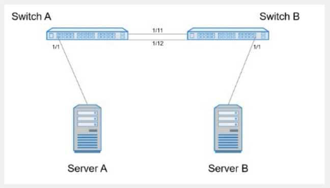

Answer:
see the
explanation for all
step by step solution
with all explanation.
Explanation:
Here are the steps to configure the required port channel and VLAN settings on Switch A:
Enter Configuration Mode:
SwitchA# configure terminal
Create Port Channel 10:
SwitchA(config)# interface port-channel 10
SwitchA(config-if-po10)# switchport mode trunk
SwitchA(config-if-po10)# switchport trunk native vlan 1
SwitchA(config-if-po10)# switchport trunk allowed vlan 1,10
Assign Interfaces Eth 1/11 and Eth 1/12 to Port Channel 10:
SwitchA(config)# interface ethernet 1/11
SwitchA(config-if-eth1/11)# channel-group 10 mode active
SwitchA(config-if-eth1/11)# exit
SwitchA(config)# interface ethernet 1/12
SwitchA(config-if-eth1/12)# channel-group 10 mode active
SwitchA(config-if-eth1/12)# exit
Configure Interface Eth 1/1 for Server Connection:
SwitchA(config)# interface ethernet 1/1
SwitchA(config-if-eth1/1)# switchport mode trunk
SwitchA(config-if-eth1/1)# switchport trunk native vlan 1
SwitchA(config-if-eth1/1)# switchport trunk allowed vlan 1,10
SwitchA(config-if-eth1/1)# end
Save Configuration:
SwitchA# write memory
Comprehensive Detailed Step by Step Explanation with Reference:
Enter Configuration Mode:
Start by entering the global configuration mode to make changes to the switch configuration.
Create Port Channel 10:
Enter the port channel interface configuration mode using interface port-channel 10.
Set the port channel to trunk mode with switchport mode trunk.
Specify VLAN 1 as the native VLAN (untagged) using switchport trunk native vlan 1.
Allow VLANs 1 and 10 on the trunk with switchport trunk allowed vlan 1,10.
Assign Interfaces Eth 1/11 and Eth 1/12 to Port Channel 10:
Enter interface configuration mode for ethernet 1/11 and ethernet 1/12.
Assign each interface to port channel 10 using the channel-group 10 mode active command.
Exit the interface configuration mode.
Configure Interface Eth 1/1 for Server Connection:
Enter interface configuration mode for ethernet 1/1.
Set the interface to trunk mode with switchport mode trunk.
Specify VLAN 1 as the native VLAN using switchport trunk native vlan 1.
Allow VLANs 1 and 10 on the trunk with switchport trunk allowed vlan 1,10.
Exit the configuration mode.
Save Configuration:
Ensure the configuration is saved so it persists after a reboot using the write memory command.
Reference:
Dell Technologies Networking - SONiC
Dell Enterprise SONiC Deployment Guide
These steps provide a comprehensive guide to configure a port channel and VLAN settings on Switch
A to meet the specified requirements for server and trunk connections.
Question 5
SIMULATION
Use the simulator to perform the following configuration task.
1. Map a single-tagged CVLAN 100 to SVLAN 200 translation on PE
switch interface Eth1/1.
2. Map a double-tagged VLAN packet with an outer CVLAN 100 and an
inner dot1q 200 to SVLAN 300 translation on PE switch interface
Eth1/2.
The necessary VLANs and VLAN stacking have already been configured.
Answer:
see the
explanation for all
step by step solution
with all explanation.
Explanation:
Here are the steps to configure the required VLAN translations on a Dell SONiC switch:
Map a Single-Tagged CVLAN 100 to SVLAN 200 on Interface Eth1/1:
sonic# configure terminal
sonic(config)# interface Ethernet1/1
sonic(config-if-Ethernet1/1)# switchport mode trunk
sonic(config-if-Ethernet1/1)# switchport vlan mapping 100 200
sonic(config-if-Ethernet1/1)# end
sonic# write memory
Map a Double-Tagged VLAN Packet with Outer CVLAN 100 and Inner dot1q 200 to SVLAN 300 on
Interface Eth1/2:
sonic# configure terminal
sonic(config)# interface Ethernet1/2
sonic(config-if-Ethernet1/2)# switchport mode trunk
sonic(config-if-Ethernet1/2)# switchport vlan mapping 100 200 300
sonic(config-if-Ethernet1/2)# end
sonic# write memory
Comprehensive Detailed Step by Step Explanation with Reference:
Enter Configuration Mode:
Access the global configuration mode using the configure terminal command.
Configure Interface Eth1/1:
Enter interface configuration mode for Ethernet1/1 using the command interface Ethernet1/1.
Set the switchport mode to trunk with the command switchport mode trunk.
Configure the VLAN translation using the switchport vlan mapping 100 200 command, which maps
CVLAN 100 to SVLAN 200.
Exit the interface configuration mode by typing end.
Save the configuration with write memory.
Configure Interface Eth1/2:
Enter interface configuration mode for Ethernet1/2 using the command interface Ethernet1/2.
Set the switchport mode to trunk with the command switchport mode trunk.
Configure the double-tagged VLAN translation using the switchport vlan mapping 100 200 300
command, which maps packets with outer CVLAN 100 and inner dot1q 200 to SVLAN 300.
Exit the interface configuration mode by typing end.
Save the configuration with write memory.
Reference:
Dell Technologies Networking - SONiC
Dell Enterprise SONiC Deployment Guide
These steps provide a comprehensive guide to configure VLAN translations on a Dell SONiC switch,
ensuring that the specific requirements for single-tagged and double-tagged VLAN mappings are
met.
Question 6
SIMULATION
Configure the system to meet these requirements.
. Configure R1 with AS 1.
. R1 must use a static neighbor assignment for BGP peering.
. R1 needs to redistribute all current and future connected IPv4 routes.
All the required BGP configurations have already been completed on R2.
R2 resides in BGP AS 2.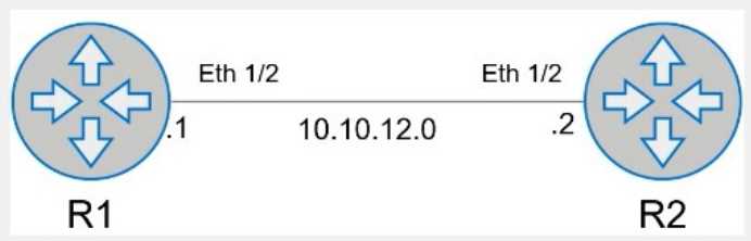

Answer:
see the
explanation for all
step by step solution
with all explanation.
Explanation:
Here is the step-by-step configuration for R1:
Enter BGP Configuration Mode:
R1# configure terminal
R1(config)# router bgp 1
Configure the BGP Neighbor:
R1(config-router)# neighbor 10.10.12.2 remote-as 2
Redistribute Connected Routes into BGP:
R1(config-router)# redistribute connected
Exit BGP Configuration Mode and Save the Configuration:
R1(config-router)# end
R1# write memory
Comprehensive Detailed Step by Step Explanation with Reference:
Enter BGP Configuration Mode:
To configure BGP on R1, you need to enter global configuration mode and then enter BGP
configuration mode with the AS number. Since R1 is in AS 1, you use the command router bgp 1.
Configure the BGP Neighbor:
BGP neighbors must be manually specified. In this case, R1's neighbor is R2, which has an IP address
of 10.10.12.2 and resides in AS 2. The command neighbor 10.10.12.2 remote-as 2 establishes this
relationship.
Redistribute Connected Routes into BGP:
To ensure that all connected routes on R1 are advertised via BGP, you use the redistribute connected
command. This ensures that any connected IPv4 routes are redistributed into BGP, meeting the
requirement to advertise current and future connected routes.
Exit BGP Configuration Mode and Save the Configuration:
Once the configuration is complete, you exit BGP configuration mode by typing end and then save
the configuration with the write memory command. This ensures that the changes persist after a
reboot.
Reference:
Cisco BGP Configuration Guide
Dell Technologies Networking - SONiC
Dell Enterprise SONiC Deployment Guide
These steps provide a comprehensive guide to configure R1 to meet the specified requirements for
BGP peering and route redistribution.
Question 7
Refer to the exhibits.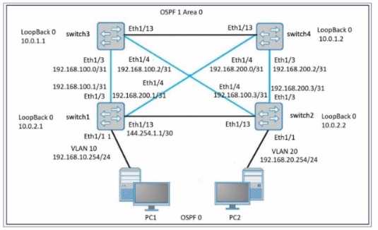
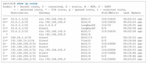
PC1 has a valid address on the 192.168.10.0 network, and PC2 has a valid address on the
192.168.20.0 network.
What happens when a ping command is issued between PC1 and PC2?
- A. The ping is successful because there is a route to 10.0.1.1, which is connected to 1(10.2.2, which is connected to PC2.
- B. The ping is unsuccessful because there is no route to the VLAN 10 gateway address of 192.168.10.254.
- C. The ping is successful because there are two routes from switch1 to switch2 which are connected to PC2.
- D. The ping is unsuccessful because there is no route from switch 1 to the 192.168.20.0 network.
Answer:
D
Explanation:
Network Topology Analysis:
PC1 is on VLAN 10 with an IP address in the 192.168.10.0/24 subnet.
PC2 is on VLAN 20 with an IP address in the 192.168.20.0/24 subnet.
The network uses OSPF for routing between the switches.
The OSPF area is 0, and all switches have loopback interfaces for OSPF.
Routing Table Examination (from switch1):
The show ip route command output from switch1 provides a detailed look at the routing table.
Routes to the 192.168.10.0/24 network (directly connected via Vlan10) are present.
No routes to the 192.168.20.0/24 network are listed in switch1's routing table.
Explanation :
For PC1 to communicate with PC2, switch1 must have a route to the 192.168.20.0/24 network.
The absence of a route to the 192.168.20.0/24 network in switch1's routing table means that switch1
cannot forward packets destined for 192.168.20.0/24.
Therefore, any ping from PC1 to PC2 will be unsuccessful as switch1 does not know how to route
packets to PC2's network.
Verification with Dell SONiC:
In Dell SONiC environments, OSPF is configured to ensure dynamic routing.
The configuration must include all necessary networks for inter-switch routing.
If a network (like 192.168.20.0/24) is not included in OSPF configurations on switch1, routes to that
network will not be advertised or learned, leading to failed connectivity tests like the ping from PC1
to PC2.
Reference:
Dell Enterprise SONiC Deployment Guide
Dell Technologies Networking - SONiC
Topic 2, SIMULATION / Lab based
Question 8
What interface must be selected when configuring the management port from within the MF-CLI
environment?
- A. mgmt 1/1/1
- B. ma 0/1
- C. Management 0
- D. eth0
Answer:
D
Explanation:
Dell SONiC Management Interface Configuration:
In Dell SONiC, the management port configuration is a crucial aspect that allows administrators to
access and manage the network device.
The management interface typically provides out-of-band management access to the device,
ensuring that even if the data network is down, the management network can still be accessed.
Common Interface Naming Conventions:
mgmt 1/1/1: This naming convention is not typically used in Dell SONiC environments for
management interfaces.
ma 0/1: This could be a potential naming convention but is not standard for Dell SONiC.
Management 0: This is a logical name but does not align with the standard interface naming
conventions used in Dell SONiC.
eth0: This is the standard naming convention used for the primary management interface in most
Linux-based systems, including Dell SONiC.
Verification with Dell SONiC Documentation:
Dell SONiC documentation specifies that the management interface is usually named eth0.
When accessing the management interface within the MF-CLI (Management Framework Command
Line Interface) environment, eth0 is the correct interface to configure.
Practical Configuration Example:
When configuring the management port, the command might look something like:
config interface ip add eth0 <management_ip_address>/<subnet_mask>
This command specifies the management interface eth0 and assigns it an IP address for network
management purposes.
Reference:
Dell Enterprise SONiC Deployment Guide
Dell Technologies Networking - SONiC
This detailed step-by-step explanation confirms that the correct answer is D, providing insights into
the typical interface naming conventions and configuration practices within the Dell SONiC
environment.
Question 9
What is the impact of entering the qos-mode uniform command on a VTEP interface?
- A. The DCSP values for the local and remote VTEPs are synchronized.
- B. The local VNI value is aligned to the VNI of the remote VTEP interface.
- C. A uniform VNI value is configured on local and remote VTEP interfaces.
- D. The payload DSCP value is copied to the outer header DSCP value.
Answer:
D
Explanation:
Entering the qos-mode uniform command on a VTEP interface ensures that the DSCP (Differentiated
Services Code Point) value of the payload is copied to the outer header DSCP value. This maintains
the Quality of Service (QoS) markings across the VXLAN tunnel, allowing consistent traffic
prioritization.
Reference:
Dell Technologies SONiC documentation
VXLAN and QoS Configuration Guide
Question 10
What is the purpose of the write erase boot command option?
- A. Delete the startup and enable zero touch provisioning.
- B. Remove user-installed packages and tile changes.
- C. Delete the startup configuration and the management interface configuration.
- D. Delete the running configuration and all user accounts.
Answer:
A
Explanation:
The write erase boot command option deletes the startup configuration and enables zero touch
provisioning (ZTP). This is used to reset the switch to its default state and prepare it for automated
configuration through ZTP.
Reference:
Dell Technologies SONiC Command Reference Guide
Switch Configuration Guide
Question 11
What is a correct use-case scenario for ZTP in Enterprise SONiC?
- A. The user wants single pane of glass monitoring.
- B. The user wants to replace a failed unit and use an automatic script.
- C. The user wants multivendor switch deployment.
- D. The user wants to configure the switch manually using the CLI.
Answer:
B
Explanation:
ZTP (Zero Touch Provisioning) is used to automate the configuration of switches, especially useful in
scenarios where a failed unit needs to be replaced. By using ZTP, the switch can automatically
download and apply the necessary configuration scripts upon boot-up, reducing the need for manual
intervention and speeding up the deployment process.
Reference:
Dell Technologies SONiC documentation
Zero Touch Provisioning Guide
Question 12
What is ECMP?
- A. A Layer 3 routing feature to forward traffic using multiple available paths
- B. A routing protocol database filter supporting a maximum of four paths
- C. A round-robin path distribution mechanism
- D. A routing protocol with multipath support
Answer:
A
Explanation:
ECMP (Equal-Cost Multi-Path) is a Layer 3 routing feature that allows traffic to be forwarded using
multiple available paths of equal cost. This improves bandwidth utilization and provides redundancy.
ECMP is commonly used in modern networks to optimize the flow of traffic and increase the
resiliency of network connections.
Reference:
Dell Technologies SONiC documentation
ECMP Configuration Guide
Question 13
Refer to the exhibit.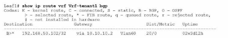
What type of route is shown?
- A. Type 3 host route from external VTEP
- B. Type 2 host route from another VTEP
- C. Type 3 host route from another VTEP
- D. Type 5 host route from another VTEP
Answer:
B
Explanation:
The exhibit shows a BGP EVPN route in a VXLAN environment. The route type can be determined
based on the details provided. Type 2 routes in BGP EVPN are used to advertise MAC address
reachability information between VTEPs (Virtual Tunnel End Points). The exhibit indicates a host
route from another VTEP, which corresponds to a Type 2 route.
Reference:
Dell Technologies SONiC documentation
BGP EVPN Configuration Guide
Question 14
What does show interface breakout port slot/slot command display?
- A. The Error/Debug status of the breakout of the port
- B. The breakout modes available to that port
- C. The In Progress/Complete status of the breakout of the port
- D. The configuration of that port
Answer:
B
Explanation:
The show interface breakout port slot/slot command displays the breakout modes available for the
specified port. Breakout modes determine how a single high-speed port can be split into multiple
lower-speed ports, providing flexibility in network port configurations.
Reference:
Dell Technologies SONiC Command Reference Guide
Port Breakout Configuration Guide
Question 15
Which protocol is used to perform an automated installation of Enterprise SONiC?
- A. HTTP
- B. SCP
- C. SFTP
Answer:
A
Explanation:
The automated installation of Enterprise SONiC is typically performed using the HTTP protocol.
During the Zero Touch Provisioning (ZTP) process, the switch retrieves configuration files and
software images from an HTTP server, allowing for automated and streamlined deployments.
Reference:
Dell Technologies SONiC documentation
ONIE User Guide