dell D-PVM-OE-01 Exam Questions
Questions for the D-PVM-OE-01 were updated on : Feb 20 ,2026
Page 1 out of 4. Viewing questions 1-15 out of 49
Question 1
SIMULATION
A PowerMax array has been added to the environment. As part of the configuration, a weekly backup
is done every Sunday during the 8:00 AM hour. The load for all components during the backup
window should not be in system-level compliance calculations.
Using the simulator, set a recurring exclusion window at the system level on the array for the backup
window.
Answer:
See the
explanation for step
by step solution.
Explanation:
Okay, I understand. We need to configure a recurring exclusion window in the Unisphere for
PowerMax simulator to exclude performance load during a weekly backup that occurs every Sunday
from 8:00 AM to 9:00 AM. This exclusion will prevent the backup load from affecting system-level
compliance calculations.
Here's a step-by-step guide on how to do this, based on typical Unisphere functionality:
Steps:
1. Launch the Simulator and Navigate to the System Settings
Open Unisphere for PowerMax in your web browser.
Log in to the simulator (you should already be logged in with the array SID 1762 selected, based on
the image).
In the left-hand navigation pane, locate the settings or configuration section. The exact location
might vary slightly, but it's often found under:
Home > System Settings
Settings (an icon representing settings, like a gear)
Admin > System
In this instance, click the gear icon on the top right corner of the Unisphere interface.
2. Find the Exclusion Window Settings
Within the system settings, look for a section related to performance monitoring, metrics, or
thresholds.
Within this section, search for an option to configure "Exclusion Windows," "Scheduled Exclusions,"
or something similar. The exact name may vary.
3. Create a New Exclusion Window
Click on a button or link to create a new exclusion window. This might be labeled:
"Create"
"Add"
"+" (a plus icon)
A new window or panel will appear, allowing you to configure the exclusion window settings.
4. Configure the Exclusion Window Settings
Name (Optional): You can give the exclusion window a descriptive name, such as "Weekly Backup
Exclusion."
Type: Select "Recurring" or "Repeating" as the exclusion window type.
Schedule:
Day of the Week: Select "Sunday".
Start Time: Set the start time to 08:00 (or 8:00 AM). Make sure the time is in 24-hour format or that
you correctly select AM if using 12-hour format.
End Time: Set the end time to 09:00 (or 9:00 AM).
Scope/Target: Since we want this exclusion to apply at the system level, make sure the scope is set to
"System" or the entire array (SID 1762 in this case). You might not need to explicitly select this if
system-level is the default.
Components/Metrics: In some Unisphere versions, you can choose which components or metrics to
exclude. In our case, we want to exclude the load for "all components." If there's an option to select
components, either choose "All" or leave it at the default (which likely includes all components).
5. Save the Exclusion Window
After configuring all the settings, review them carefully to make sure they are correct.
Click the button to save the exclusion window. This might be labeled:
"Create"
"Save"
"OK"
"Apply"
6. Verify Exclusion Window Creation (Optional)
After the exclusion window is created, you can usually verify its settings in the exclusion window list.
You should see the new exclusion window listed with the correct schedule (Sunday, 8:00 AM - 9:00
AM) and scope (system level).
Question 2
SIMULATION
Your organization is preparing for a major software update, and it is crucial to ensure data integrity
during this process. As a system administrator, create a secure snapshot named "Stor1" from the
storage group "StorGroup1." The snapshot cannot be deleted for two days to safeguard against any
potential data loss during the update.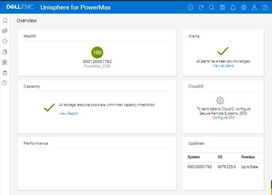
Using the simulator, complete the operation.
Answer:
See the
explanation for step
by step solution.
Explanation:
We need to create a secure snapshot named "Stor1" from the storage group "StorGroup1" in the
Unisphere for PowerMax simulator, and the snapshot should be protected from deletion for two
days.
Here's a step-by-step guide on how to do this, based on typical Unisphere functionality:
Steps:
1. Launch the Simulator and Navigate to the Storage Groups Section
Open Unisphere for PowerMax in your web browser.
Log in to the simulator (you should already be logged in with the array SID 1762 selected).
In the left-hand navigation pane, click on Storage and then select Storage Groups.
2. Locate and Select "StorGroup1"
In the Storage Groups view, you'll see a list of all storage groups on the array.
Find the storage group named "StorGroup1".
Click on the name "StorGroup1" to open its details view.
3. Initiate the Snapshot Creation Process
Within the "StorGroup1" details view, look for an option related to creating snapshots or protecting
the storage group. This might be a button labeled:
"Protect"
"Create Snapshot"
"SnapVX"
Or an icon representing snapshot creation.
Click the appropriate button or icon to start the snapshot creation process.
4. Configure Snapshot Settings
A new window or panel will appear, allowing you to configure the snapshot settings.
Snapshot Name: Enter Stor1 as the snapshot name.
Snapshot Technology: Select SnapVX (or a similar option) as the snapshot technology.
Secure Snapshot: This is crucial. Look for an option labeled "Secure Snapshot," "Enable Secure Snap,"
"Secure Snap," or something similar. Check this option.
Retention/Expiration: You need to set the retention period for the secure snapshot. This will define
how long the snapshot cannot be deleted. There are usually a few ways to configure this:
Expiration Time: Set an explicit expiration date and time that is two days from now.
Retention Period: Specify a retention period of 2 days.
No Expiry: This option is not what we want here. We want the snap to be secure for 2 days.
Choose the appropriate option to make the snapshot undeletable for two days.
Other Settings: Review any other available settings. You might be able to choose between creating a
new snapshot or linking to an existing one. Select the option to create a new snapshot.
5. Create the Snapshot
After configuring all the snapshot settings, review them carefully to ensure they are correct.
Click the button to create the snapshot. This button might be labeled:
"Run Now"
"OK"
"Create"
"Finish"
6. Verify Snapshot Creation (Optional)
After the snapshot creation operation completes, you can verify that the snapshot was created
successfully:
Go back to the "StorGroup1" details view.
Look for a tab or section related to snapshots (e.g., "Snapshots," "TimeFinder," "Local Replication").
You should see the "Stor1" snapshot listed there, and its status should indicate that it's a secure
snapshot with the correct retention period (2 days).
Question 3
SIMULATION
A customer has a clone session for the storage group DATA that is no longer needed.
Using the simulator, terminate the clone session for the storage group.
Answer:
See the
explanation for step
by step solution.
Explanation:
We need to terminate a clone session for the storage group named "DATA" in the Unisphere for
PowerMax simulator.
Here's a step-by-step guide on how to do this, based on typical Unisphere functionality and the
context of the
question:
Steps:
1. Launch the Simulator and Navigate to the TimeFinder/Clone Section
Open Unisphere for PowerMax in your web browser.
Log in to the simulator (you should already be logged in with the array SID 1762 selected, based on
the provided image).
In the left-hand navigation pane, locate the section related to TimeFinder operations. This is usually
found under:
Data Protection
Local Protection
TimeFinder
Expand the relevant sections and click on TimeFinder SnapVX or TimeFinder Clone (the exact
wording might vary slightly in the simulator). The goal is to get to the view where you can manage
clone sessions.
2. Locate the Clone Session for the "DATA" Storage Group
The TimeFinder/Clone view will display a list of existing clone sessions.
You need to find the session associated with the "DATA" storage group. Look for the following:
Storage Group Name: The "DATA" storage group should be listed as the source of the clone session.
Session Type/Mode: Verify that it's a Clone session (not a SnapVX snapshot or another type of
session).
3. Select the Clone Session
Once you've found the correct clone session for the "DATA" storage group, select it.
You can usually do this by:
Clicking a checkbox next to the session.
Clicking on the session itself (if the interface allows it).
4. Terminate the Clone Session
After selecting the clone session, look for an action button or menu option to terminate it. This might
be labeled:
"Terminate"
"Delete"
"Remove"
"Fracture" (in some older versions)
"Stop"
Click the appropriate button to initiate the termination process.
Confirmation: You will likely be prompted with a confirmation message to ensure you want to
terminate the selected clone session. Verify that you have selected the correct session (the one for
the "DATA" storage group) and confirm the termination.
Question 4
SIMULATION
The web application server web_host_1 is deprecated. Remove all resources associated with the
host to clean up the environment.
Using the simulator, complete the task.
Answer:
See the
explanation for step
by step solution.
Explanation:
We need to remove all resources associated with a deprecated web application server named
web_host_1 in the Unisphere for PowerMax simulator.
Here's a step-by-step guide on how to accomplish this, based on typical Unisphere functionality and
the context of the
question:
Steps:
1. Launch the Simulator and Navigate to the Hosts Section
Open Unisphere for PowerMax in your web browser.
Log in to the simulator.
In the left-hand navigation pane, click on Hosts > Hosts. This will take you to the Hosts management
view.
2. Locate the Host web_host_1
In the Hosts view, you'll see a list of all configured hosts.
Find the host named web_host_1. You might need to use the search or filtering options if there are
many hosts listed.
3. Identify Associated Resources
Before deleting the host, it's crucial to identify all resources associated with it. These typically
include:
Masking Views: These define the LUNs that a host can access.
Storage Groups: These contain the volumes presented to the host.
Port Groups: These define the connectivity paths (ports) used by the host.
How to Find Associated Resources:
Click on the web_host_1 host entry. This should open a details view or properties page for the host.
Look for tabs or sections labeled "Masking Views," "Storage Groups," or similar.
Note down the names of any masking views and storage groups associated with web_host_1.
4. Remove the Host from Masking Views
Navigate to Hosts > Masking Views.
Locate the masking views that you identified in Step 3 as being associated with web_host_1.
Open each masking view's properties.
Remove the Host: There should be an option to edit the host list within the masking view. Find
web_host_1 in the list of hosts and remove it.
Save Changes: Save the changes to the masking view.
Repeat for all masking views associated with web_host_1.
5. Delete or Modify Storage Groups
Navigate to Storage > Storage Groups.
Locate the storage groups that were associated with web_host_1.
Two Options:
If the storage group is ONLY used by web_host_1: You can delete the entire storage group. Select the
storage group and click the Delete button (or a similar option).
If the storage group is shared with other hosts: You need to remove the volumes associated with
web_host_1 from the storage group.
Open the storage group's properties.
Go to the "Volumes" tab.
Identify the volumes that were presented to web_host_1.
Select those volumes and choose the option to "Remove from Storage Group" or a similarly worded
option.
Save the changes to the storage group.
6. Delete the Host
Go back to Hosts > Hosts.
Select web_host_1.
Click the Delete button (or a similar option, like a trashcan icon).
Confirm that you want to delete the host.
7. Verify Removal (Optional)
After deleting the host and modifying the storage groups and masking views, you can verify that the
resources have been properly cleaned up.
Check the Storage Groups and Masking Views sections again to ensure that web_host_1 is no longer
listed and that the storage groups have been either deleted or modified as intended.
Question 5
SIMULATION
The customer has successfully completed a Non-Disruptive Migration.
Use the simulator to verify migration sessions and remove the migration environment.
Answer:
See the
explanation for step
by step solution.
Explanation:
Okay, I understand. The task is to verify the completion of Non-Disruptive Migrations (NDM) and
then remove the migration environment using the Unisphere for PowerMax simulator.
Here's a step-by-step guide on how to do this, based on typical Unisphere functionality and the
context of the
question:
Steps:
1. Launch the Simulator and Navigate to the Migration Section
Open Unisphere for PowerMax in your web browser.
Log in to the simulator.
In the left-hand navigation pane, locate the section related to migrations. This is usually under either:
Data Mobility
Migration
Expand the relevant section and click on Migrations (or a similar option like "Local Migrations" or
"NDM"). This will take you to the view where you can manage Non-Disruptive Migrations.
2. Verify Migration Session Status
The Migrations view will list all current and past migration sessions.
Look for the following status indicators to confirm that the migrations have completed successfully:
Status: The status should typically be "Completed," "Cutover Complete," or a similar status indicating
successful completion.
Progress: If a progress bar or percentage is shown, it should be at 100% or show that all data has
been synchronized.
Important: If any sessions are still in a "Running," "Synchronizing," or other non-completed state, do
not proceed with removing the migration environment. Wait for them to complete.
3. Select Completed Migrations for Removal
Once you've verified that all relevant migration sessions are successfully completed, select the
sessions that you want to remove.
You can usually select sessions by:
Clicking a checkbox next to each session.
Clicking on the session itself (if the interface allows it).
4. Remove the Migration Environment
After selecting the completed migration sessions, look for an action button or menu option to
remove them. This might be labeled:
"Remove"
"Delete"
"Cleanup"
"Remove Session"
Click the appropriate button to initiate the removal process.
Confirmation: You will likely be prompted with a confirmation message to make sure you want to
remove the selected migration sessions. Verify that you have selected the correct sessions and
confirm the removal.
5. Verify Removal (Optional)
After the removal operation completes, the Migrations view should refresh.
Verify that the migration sessions you removed are no longer listed.
Question 6
SIMULATION
A company is preparing for a major product launch and a quarterly compliance audit. Perform a
system health check to ensure that the storage array with SID - 1762 is functioning optimally, and
also review the compliance status, generate and download the compliance report for all SGs.
Use the simulator to complete these tasks.
Answer:
See the
explanation for step
by step solution.
Explanation:
Okay, I understand. We need to perform a system health check and review the compliance status for
a PowerMax array with SID ending in 1762 using the Unisphere simulator, then generate and
download a compliance report.
Here's how you would do it in the Unisphere for PowerMax simulator, based on the provided image
and common Unisphere functionality:
Steps:
1. Launch the Simulator and Access the System Health View
Open Unisphere for PowerMax in your web browser.
You should already be logged in to the simulator, with the PowerMax array with SID 1762.
The initial Overview page (as shown in the image) provides a good starting point for a health check.
2. Analyze the Overview Page
Health: The "Health" section displays the overall health status of the array. In the image, it shows
"100" with a green checkmark, which indicates that the array is currently healthy.
Alerts: The "Alerts" section will show if there are any active alerts. In the image, it shows a green
checkmark and "All alerts have been acknowledged," meaning no unacknowledged alerts. You can
click "View all Alerts" to see the alert history.
Capacity: The "Capacity" section indicates whether storage resource pools are within their capacity
thresholds. The green checkmark and "All storage resource pools are within their capacity
thresholds" message indicate that capacity is currently healthy. You can click "View Report" for more
details.
Performance: The "Performance" section is not detailed in the image, but it would typically provide a
quick overview of the array's performance.
Updates: The "Updates" section shows the system's PowerMaxOS code level and whether any
updates are overdue. In the image, it shows that the system is "Up to Date."
3. Navigate to the Compliance Section
In the left-hand navigation pane, click on Data Protection to expand it.
Click on Compliance under Data Protection.
4. Review Compliance Status
The Compliance view will show you the overall compliance status of your storage groups against the
defined compliance policies.
Review the compliance status for each Storage Group.
Look for any storage groups that are marked as "Non-Compliant."
5. Generate the Compliance Report
Click on "Generate Report" (or a similarly worded button) within the Compliance view. This might
also be represented as an icon in the simulator.
Select all Storage Groups Since we need to generate the report for all storage groups.
Report Format: Choose the desired report format. Common options are usually PDF, CSV, or HTML.
For this simulation, let's assume PDF is available and select it.
Download the Report: Once the report is generated, there will typically be a "Download" or similar
option to save the report to your local system. Click it to download the compliance report.
6. Further Health Checks (Optional):
Detailed Performance Metrics: You can navigate to the Performance section in the left navigation
pane (under "Dashboard") to view more detailed performance metrics for various components of the
array.
Hardware Status: You can typically find a "Hardware" section (or similarly named section) that
provides information about the physical components of the array (e.g., DAEs, directors, ports).
Question 7
SIMULATION
A company is setting up a multi-tenant environment where multiple departments share the same
storage array with SID 1762. The IT department requires 2 TB of storage to be available on the ESXi1
host. Use "ESXi1_SG" for the storage group name, create a port group with Dir- Ports "OR-1C:0 and
OR-2C:0," and leave all other settings at their default.
Using the simulator, provision the storage required with a single volume using auto-provisioning
groups.
Answer:
See the
explanation for step
by step solution.
Explanation:
We need to provision 2 TB of storage to the ESXi1 host on a PowerMax array (SID 1762) using
Unisphere, in a multi-tenant environment. We'll use auto-provisioning with the following specifics:
Storage Group Name: ESXi1_SG
Port Group: (A new port group with Directors OR-1C:0 and OR-2C:0)
Volume Size: 2 TB (single volume)
Other Settings: Default
Here are the step-by-step instructions, tailored for the Unisphere simulator as described in the
question:
Steps:
1. Launch the Simulator and Navigate to Storage Groups
Open Unisphere for PowerMax in your web browser.
You should already be logged in to the simulator, with the PowerMax array with SID 1762.
In the left-hand navigation pane, click on Storage > Storage Groups.
2. Initiate Storage Group Creation
Click the Create button (likely a plus "+" icon) in the Storage Groups section to start the Create
Storage Group wizard.
3. Name the Storage Group
In the "Create Storage Group" wizard:
Storage Group Name: Enter ESXi1_SG.
Enable FAST/Service Level: Do not check this option, as we are leaving all other settings at their
default.
Click Next or Continue (the exact wording might vary).
4. Add Volumes
Ensure "Create new volumes" is selected.
Number of Volumes: Enter 1.
Volume Size:
Enter 2.
Select TB from the dropdown for the unit.
Click Next.
5. Create the Port Group
You should now be on the "Connectivity" or "Host" step, where you will add a new port group.
Select "Create Port Group"
Port Group Name: Give the new port group a name. You can use something descriptive like
"ESXi1_PG," or any name that follows your organization's naming conventions.
Select Ports:
Find and select the following Directors and ports from the list of available ports:
OR-1C:0
OR-2C:0
Note: The simulator may not allow you to highlight the exact director ports as in a production
environment. It will likely display all directors and ports under the selected array. Just ensure they
are selected as part of the port group.
Click Next.
6. Add host to the Masking View
Select "Add Host"
Select "Create New Host"
Host Name: ESXi1
Initiators: You don't have specific initiators to add in this simulation, so you can skip this part or add
any from the available options. This is because we are working within a simulated environment.
Click Next
7. Review and Create
You'll be presented with a summary page that shows:
Storage Group: ESXi1_SG
Volume: 1 x 2 TB volume
Port Group: (The new port group you created with OR-1C:0 and OR-2C:0)
Host: ESXi1
Carefully review all the settings to make sure they are correct.
Click Run Now or Finish (or similar wording) to create the storage group, volume, port group, and
masking view.
8. Verification (Optional)
After the operation completes, you can verify the results:
Go back to the Storage Groups list. You should see the ESXi1_SG storage group.
Click on ESXi1_SG to view its details. You should see the 2 TB volume and the associated host (ESXi1)
and port group.
You can also navigate to Hosts > Port Groups to verify that the new port group was created correctly.
Finally, you can navigate to Hosts > Masking Views to verify that a masking view was created
correctly.
Question 8
SIMULATION
A customer has an existing host with two 100 GB volumes that are assigned from existing PowerMax
storage. They would like to add three additional volumes of 100 GB each and change the service
level that is assigned to the storage group from Gold to Platinum to support the current application
SLO requirements.
Answer:
See the
explanation for step
by step solution.
Explanation:
You want a detailed, step-by-step guide on how to add three 100 GB volumes to an existing host and
change the service level of the associated storage group from Gold to Platinum on a PowerMax array,
using the Unisphere for PowerMax interface shown in the image.
Here's a comprehensive guide, broken down into manageable steps:
Phase 1: Provisioning the New Volumes
Step 1: Log in to Unisphere for PowerMax
Open your web browser and enter the URL for your Unisphere for PowerMax management interface.
Log in with your administrator credentials.
Step 2: Navigate to Storage Groups
In the left-hand navigation pane, click on Storage to expand the storage management section.
Click on Storage Groups under the Storage section. This will display a list of existing storage groups
on your PowerMax array.
Step 3: Locate the Target Storage Group
Identify the storage group that currently contains the host's existing two 100 GB volumes.
Tip: You can find this by:
Looking at the "Hosts" tab within each storage group's details. It will list the hosts connected to that
storage group.
If you know the host's name, you might be able to search for it using the Unisphere search bar (if
available).
Step 4: Initiate Adding Volumes
Once you've found the correct storage group, select it by clicking on its name.
Look for a button or option related to adding volumes. The exact wording might vary slightly
depending on your Unisphere version, but it could be:
"Add to Storage Group"
"+" (a plus icon, which often signifies adding something)
"Add Volumes"
Click this button to start the process of adding new volumes to the storage group.
Step 5: Configure Volume Details
A new window or panel will appear, allowing you to specify the characteristics of the new volumes.
Select "Create new volumes"
Number of Volumes: Enter 3 in the field for the number of volumes.
Capacity: Enter 100 in the field for the capacity of each volume. Make sure the unit is set to GB.
Volume Name (Optional): You can give the volumes a specific name or prefix, or you can let
Unisphere auto-generate names.
Service Level: Since the final goal is to move the entire Storage Group to platinum, you can either set
this to platinum now or change it for the whole group later.
Other Settings: Review any other available settings (e.g., thin provisioning, data reduction). In most
cases, the default settings should be fine, but adjust them if needed based on your environment's
best practices.
Step 6: Execute Volume Creation
After you've configured all the volume settings, review them carefully to make sure they are correct.
Click the button to execute the operation. This button might be labeled:
"Run Now"
"OK"
"Finish"
"Apply"
Unisphere will start creating the new volumes. This might take a few moments.
Phase 2: Changing the Storage Group's Service Level
Step 7: Navigate Back to Storage Groups
Once the volume creation is complete, go back to the list of storage groups. You can usually do this
by clicking "Storage Groups" in the left-hand navigation pane again.
Step 8: Select the Target Storage Group
Find the same storage group you worked with in Phase 1 (the one containing the host's volumes).
Click on the storage group's name to open its properties.
Step 9: Modify the Service Level
Look for a setting related to the "Service Level." It might be a dropdown menu, a field you can edit,
or a link to a separate settings page.
Change the Service Level from Gold to Platinum.
Step 10: Save the Changes
Click the button to save the changes to the storage group's service level. This button might be
labeled:
"Apply"
"Save"
"OK"
Phase 3: Host-Side Configuration
Step 11: Rescan for New Storage on the Host
The host needs to be made aware of the newly provisioned storage. The exact process for this
depends on the host's operating system:
Windows:
Open Disk Management (diskmgmt.msc).
Go to Action > Rescan Disks.
Linux:
Identify the SCSI host bus numbers (e.g., ls /sys/class/scsi_host).
Use the command echo "- - -" > /sys/class/scsi_host/hostX/scan, replacing hostX with the appropriate
host bus number.
You might also be able to use tools like rescan-scsi-bus.sh.
VMware ESXi:
In the vSphere Client, select the host.
Go to Configure > Storage Adapters.
Select the relevant storage adapter (e.g., your HBA).
Click Rescan Storage.
Step 12: Initialize, Partition and Mount (if needed):
Once the host detects the new volumes, you'll need to initialize them, create partitions, format them
with a filesystem, and mount them, depending on your operating system and how you intend to use
the storage. This is done using the host's operating system tools.
Phase 4: Verification and Monitoring
Step 13: Verify in Unisphere
Go back to the storage group in Unisphere and check the "Volumes" tab. You should see the three
new 100 GB volumes listed along with the original two, and they should all have the "Platinum"
service level.
Step 14: Verify on the Host
Confirm that the host can see and access the new volumes.
Step 15: Monitor Performance
After making these changes, monitor the performance of the storage group and the application using
Unisphere's performance monitoring tools. Ensure that the Platinum service level is meeting your
application's requirements
Question 9
What is the largest TDEV PowerMaxOS 5978 can create?
- A. 32 TB
- B. 64TB
- C. 128 TB
- D. 256TB
Answer:
B
Explanation:
Step by Step Comprehensive Detailed
In PowerMaxOS 5978, the largest TDEV (Thin Device) that can be created is 64 TB. This represents the
maximum size for a single, thinly provisioned storage volume on a PowerMax array running that
version of the operating system.
Reference and documents of Dell's public documentation for PowerMax Operate v.2:
Dell PowerMax Family: Essentials and Best Practices Guide: This guide provides an overview of
PowerMax features and capabilities, including information about storage device sizes and limits.
Dell Solutions Enabler 10.0.0 CLI User Guide: This guide might contain details about the maximum
size of TDEVs that can be created using SYMCLI commands.
Topic 2,
SIMULATION
Question 10
What input is required when registering an ESXi server in Unisphere for PowerMax?
- A. Unisphere credentials and hostname
- B. IP address and hostname
- C. IP address and ESXi server credentials
- D. ESXi server credentials and Unisphere credentials
Answer:
C
Explanation:
Step by Step Comprehensive Detailed
To register an ESXi server in Unisphere for PowerMax, you need to provide the following information:
IP Address: The IP address of the ESXi server that you want to manage. This allows Unisphere to
communicate with the ESXi host.
ESXi Server Credentials: The username and password of an account with sufficient privileges to
access and manage the ESXi server. This ensures that Unisphere has the necessary permissions to
perform storage-related operations on the ESXi host.
Why other options are incorrect:
A . Unisphere credentials and hostname: Unisphere credentials are used to log in to Unisphere itself,
not to register an ESXi server.
B . IP address and hostname: While the hostname might be helpful, the ESXi server credentials are
essential for authentication and authorization.
D . ESXi server credentials and Unisphere credentials: Unisphere credentials are not required for
registering an ESXi server.
Reference and documents of Dell's public documentation for PowerMax Operate v.2:
Dell PowerMax and VMware vSphere Configuration Guide: This guide provides detailed instructions
on how to register and manage ESXi servers in Unisphere for PowerMax. You can find this document
on the Dell Support website by searching for "PowerMax and VMware vSphere Configuration Guide."
Dell Unisphere for PowerMax 10.0.0 Online Help: The online help for Unisphere might also provide
guidance on registering ESXi servers.
Question 11
What is the functionality of the storstpd Solutions Enabler daemon?
- A. Collects and manages performance statistics.
- B. Coordinates storage array locks and application syscalls
- C. Starts the system watchdog timer periodically
- D. Performs remote Solutions Enabler API functions.
Answer:
A
Explanation:
Step by Step Comprehensive Detailed
Solutions Enabler (SE) uses various daemons (background processes) to perform different functions.
The storstpd daemon is specifically responsible for:
Collecting Performance Statistics: It gathers performance data from the connected storage arrays,
such as I/O rates, response times, and other metrics.
Managing Performance Data: It stores and manages the collected performance statistics, making
them available for monitoring and analysis through tools like Unisphere for PowerMax.
This data is crucial for understanding the performance of the storage arrays, identifying potential
bottlenecks, and optimizing storage resources.
Why other options are incorrect:
B . Coordinates storage array locks and application syscalls: This is the function of the storapid
daemon.
C . Starts the system watchdog timer periodically: This is not directly related to the storstpd daemon.
D . Performs remote Solutions Enabler API functions: This is typically handled by the storsrvd
daemon.
Reference and documents of Dell's public documentation for PowerMax Operate v.2:
Dell Solutions Enabler 10.0.0 CLI User Guide: This guide provides information about the different
daemons used by Solutions Enabler and their roles. You can find this document on the Dell Support
website by searching for "Solutions Enabler CLI User Guide."
Question 12
From an application perspective, what should be done before performing an SRDF/S Restore
operation?
- A. Continue accessing the R1 devices Stop accessing the R2 devices.
- B. Stop accessing the R1 devices Continue accessing the R2 devices
- C. Stop accessing the R1 and R2 devices.
- D. Continue accessing the R1 and R2 devices
Answer:
C
Explanation:
Step by Step Comprehensive Detailed
Before performing an SRDF/S (synchronous) Restore operation, it is crucial to stop all host I/O activity
to both the R1 (source) and R2 (target) devices. This ensures data consistency and prevents potential
data loss or corruption during the restore process.
Here's why:
Data Integrity: An SRDF/S Restore operation involves copying data from the R1 device to the R2
device, overwriting any existing data on R2. If hosts are actively accessing and modifying data on
either device during this process, it can lead to inconsistencies and data integrity issues.
Synchronization: SRDF/S maintains real-time synchronization between the R1 and R2 devices. 1
Performing a Restore operation while hosts are writing data can disrupt this synchronization and lead
to unpredictable results.
Why other options are incorrect:
A . Continue accessing the R1 devices. Stop accessing the R2 devices: This would leave R1 vulnerable
to data inconsistencies.
B . Stop accessing the R1 devices. Continue accessing the R2 devices: This would make R2 susceptible
to data loss or corruption.
D . Continue accessing the R1 and R2 devices: This is the most dangerous option, as it would likely
lead to data integrity issues.
Reference and documents of Dell's public documentation for PowerMax Operate v.2:
Dell Solutions Enabler 10.0.0 SRDF Family CLI User Guide: This guide provides detailed information
about SRDF operations, including Restore. It emphasizes the importance of halting host I/O before
performing such operations to ensure data consistency. You can find this document on the Dell
Support website by searching for "Solutions Enabler SRDF Family CLI User Guide."
Dell PowerMax Family: Essentials and Best Practices Guide: This guide may offer general information
about SRDF management and best practices, which would include recommendations for performing
operations like Restore safely.
Question 13
What is the default size of a Gatekeeper on a PowerMax array1?
- A. 3 KB
- B. 3 cylinder
- C. 6 KB
- D. 6 cylinder
Answer:
B
Explanation:
Step by Step Comprehensive Detailed
A Gatekeeper in PowerMax is a small, dedicated device used for communication between the
storage array and Solutions Enabler (SYMCLI), the command-line management interface. The default
size of a Gatekeeper on a PowerMax array is 3 cylinders.
While the size can technically be specified in kilobytes (KB), the traditional and preferred unit for
Gatekeeper size is cylinders. This is because cylinders represent a specific number of blocks on the
physical disks, and using cylinders helps ensure consistent sizing across different disk types and
configurations.
Why other options are incorrect:
A . 3 KB, C. 6 KB: These sizes are too small to be practical for a Gatekeeper.
D. 6 cylinder: While older VMAX models might have used 6 cylinders, the current default for
PowerMax is 3 cylinders.
Reference and documents of Dell's public documentation for PowerMax Operate v.2:
Dell Solutions Enabler 10.0.0 CLI User Guide: This guide provides information about Gatekeepers and
their role in Solutions Enabler. While it might not explicitly state the default size, it mentions that
Gatekeepers are typically small devices. You can find this document on the Dell Support website by
searching for "Solutions Enabler CLI User Guide."
Dell PowerMax Family: Essentials and Best Practices Guide: This guide might offer general
information about Solutions Enabler and its configuration, which can provide context for
understanding the purpose and sizing of Gatekeepers.
Question 14
What is the maximum capacity per array in a PowerMax 8500?
- A. 8 PBe
- B. 18 PBe
- C. 20 PBe
- D. 24 PBe
Answer:
D
Explanation:
Step by Step Comprehensive Detailed
The PowerMax 8500 is a high-end storage array designed for enterprise environments with
demanding capacity requirements. The maximum capacity per array in a PowerMax 8500 is 24
petabytes effective (PBe).
This means that after considering data reduction technologies like deduplication and compression,
the array can store up to 24 petabytes of usable data.
Why other options are incorrect:
A . 8 PBe, B. 18 PBe, C. 20 PBe: These values are lower than the actual maximum capacity of the
PowerMax 8500.
Reference and documents of Dell's public documentation for PowerMax Operate v.2:
Dell PowerMax 8500 Hardware Information Guide: This guide provides detailed technical
specifications for the PowerMax 8500, including its maximum capacity. You can find this document
on the Dell Support website by searching for "PowerMax 8500 Hardware Information Guide."
Dell PowerMax Family: Essentials and Best Practices Guide: This guide offers a general overview of
the PowerMax family, including the 8500 model and its key features and capabilities.
Question 15
What function can a storage administrator enable on the Port Attributes page?
- A. Manage Protocol
- B. Select Mgt Option
- C. Volume Set Addressing
- D. ORS Ceiling
Answer:
B
Explanation:
Step by Step Comprehensive Detailed
The Port Attributes page in Unisphere for PowerMax allows storage administrators to configure
various settings related to the front-end ports on the storage array. One of the functions available on
this page is Select Mgt Option.
This option allows you to specify how the port is used for management purposes:
Dedicated Management Port: You can designate a port as a dedicated management port, which is
used exclusively for communication with management tools like Unisphere and Solutions Enabler.
Shared Management Port: You can configure a port to be shared for both management traffic and
host I/O traffic.
This flexibility allows you to optimize port usage and segregate management traffic if needed.
Why other options are incorrect:
A . Manage Protocol: Protocol settings (like FC or iSCSI) are typically configured elsewhere in
Unisphere, not on the Port Attributes page.
C . Volume Set Addressing: Volume Set Addressing is a feature related to mainframe connectivity and
is not directly managed through the Port Attributes page.
D . ORS Ceiling: ORS (Open Replicator Solutions) settings are managed separately and not through
the Port Attributes page.
Reference and documents of Dell's public documentation for PowerMax Operate v.2:
Dell Unisphere for PowerMax 10.0.0 Online Help: The online help for Unisphere provides detailed
information about the Port Attributes page and the available configuration options, including the
"Select Mgt Option" function. You can access this help within Unisphere itself or on the Dell Support
website.
Dell PowerMax Family: Essentials and Best Practices Guide: This guide may offer general information
about port management and configuration in PowerMax.