dell D PST MN A 24 Exam Questions
Questions for the D PST MN A 24 were updated on : Feb 20 ,2026
Page 1 out of 5. Viewing questions 1-15 out of 61
Question 1
When looking at the base enclosure front view, what does a solid amber drive LED indicate?
- A. Faulted drive
- B. Normal activity
- C. Rebuild activity
- D. Discover new drive
Answer:
A
Explanation:
When observing the base enclosure front view of a Dell PowerStore system, a solid amber drive LED
is an indication of a faulted drive.
This LED status is used to alert the storage administrator that there
is a fault within the drive that requires attention12
.
The LED states for the Dell PowerStore base enclosure are as follows:
Blue: Power is on, and no fault has occurred.
Solid Amber: Power is on, and a fault has occurred within the enclosure.
Blue after Amber Alternating: Power is on, but the system is not initialized.
Off: Power is off.
In the event of a solid amber LED, the recommended steps are:
Identify the faulted drive: Look for the drive with the solid amber LED.
Check the PowerStore Manager: Use the PowerStore Manager to identify the specific error or fault
code associated with the drive.
Follow the troubleshooting steps: Refer to the Dell PowerStore Troubleshooting Guide for detailed
steps on resolving the issue with the faulted drive.
Replace the drive if necessary: If the drive is determined to be faulty and cannot be recovered, follow
the Dell PowerStore Hardware Information Guide for instructions on safely replacing the drive.
For more detailed information and guidance, refer to the official Dell PowerStore documentation,
such as the PowerStore Hardware Information Guide and the PowerStore Troubleshooting Guide, or
contact Dell support directly
Question 2
Which account credentials are needed to run diagnostic commands?
- A. console
- B. service
- C. root
- D. admin
Answer:
B
Explanation:
The account credentials needed to run diagnostic commands on Dell PowerStore Maintenance are
for the service account.
The service account is specifically designed for performing specialized service functions, including
running diagnostic commands1
.
To run service commands, you would typically:
Enable SSH in PowerStore Manager under Settings.
Use an SSH client to connect to the management IP.
Log in using the username and password for the service account2
.
The service account has the necessary permissions to execute service scripts and commands that are
used for diagnostics and troubleshooting3
.
It is important to note that the service account password should be changed from the default during
the initial configuration of the appliance for security purposes1
.
For more detailed information on using the service account for diagnostics and other service tasks,
refer to the Dell PowerStore Service Scripts Guide or contact Dell Support.
Question 3
What describes the SAS cabling when adding an expansion enclosure to a Dell EMC PowerStore, for
each node and expansion enclosure side?
- A. SAS cabling goes from existing B ports to new A ports. At the last enclosure, SAS cabling returns from the B ports to the alternate node's A ports.
- B. SAS cabling goes from existing A ports to new B ports. At the last enclosure, SAS cabling returns from the A ports to the originating node's B ports.
- C. SAS cabling goes from existing B ports to new A ports. At the last enclosure, SAS cabling returns from the B ports to the originating node's A ports.
- D. SAS cabling goes from existing A ports to new B ports. At the last enclosure, SAS cabling returns from the A ports to the alternate node's B ports.
Answer:
D
Explanation:
The correct description of the SAS cabling when adding an expansion enclosure to a Dell EMC
PowerStore, for each node and expansion enclosure side, is Option D: SAS cabling goes from existing
A ports to new B ports. At the last enclosure, SAS cabling returns from the A ports to the alternate
node’s B ports.
When adding a SAS expansion enclosure to a Dell EMC PowerStore system, the cabling must be done
in a specific manner to ensure proper connectivity and performance.
The SAS cabling should start from the existing A ports on the base enclosure and connect to the new
B ports on the expansion enclosure1
.
At the last expansion enclosure in the chain, the SAS cabling should return from the A ports back to
the B ports on the alternate node1
.
This cabling method ensures that each node is connected to each expansion enclosure and that the
enclosures are daisy-chained correctly for optimal performance and redundancy1
.
For detailed cabling instructions and diagrams, it is recommended to consult the Dell PowerStore
Installation and Service Guide or contact Dell EMC support for assistance.
Question 4
A Storage Administrator has an existing single appliance Dell EMC PowerStore 3000T cluster. An
additional PowerStore 9000T has been purchased to add into the existing cluster.
How does the administrator proceed?
- A. Add the new 9000T appliance into the cluster per the procedure; mixed models of the same type are supported
- B. Additional VLT links on the ToR switching must be configured for the 9000T to support the increased inter-switch network load
- C. The new appliance cannot be added to the cluster; appliance model and type must match when clustering appliances together
- D. Remove two of the four NVMe NVRAM drives from the 9000T; the caching configuration of all clustered appliances must match
Answer:
A
Explanation:
The correct procedure for a Storage Administrator to add a new PowerStore 9000T appliance into an
existing single appliance Dell EMC PowerStore 3000T cluster is to add the new 9000T appliance into
the cluster per the procedure; mixed models of the same type are supported.
Dell PowerStore allows for the addition of appliances to an existing cluster, enabling both scaling up
and scaling out.
When adding a new appliance to an existing cluster, it is important to ensure that the appliance is
uninitialized and that both the new appliance and the existing cluster are in a healthy state1
.
The process of adding an appliance is facilitated through the PowerStore Manager.
The administrator
should navigate to the Hardware page and click the Add button to present the available unconfigured
appliances that can be added1
.
It is not necessary to configure additional VLT links on the ToR switching specifically for the 9000T to
support the increased inter-switch network load as part of the initial addition process1
.
There is no requirement that the appliance model and type must match when clustering appliances
together, allowing for mixed models of the same type within a cluster1
.
Removing NVMe NVRAM drives from the 9000T is not a standard procedure for clustering and is not
required for the caching configuration of all clustered appliances to match1
.
For detailed procedures on adding appliances to a Dell EMC PowerStore cluster, it is recommended
to refer to the official Dell PowerStore Clustering and High Availability documentation or contact Dell
EMC support for guidance.
Question 5
What does the output of the command "svc_diag list -- basic" show?
- A. Failover status
- B. Service tag
- C. Boot mode
- D. License status
Answer:
B
Explanation:
The output of the command “svc_diag list – basic” on a Dell PowerStore system typically shows
service tag information.
The “svc_diag” command is part of the service scripts provided by Dell for diagnostic purposes on
PowerStore systems.
The “list” option with the “–basic” flag is used to display a list of basic system information, which
usually includes the service tag, among other details.
The service tag is a unique identifier for Dell products that is used for various purposes, including
support and maintenance.
While the exact output of the command can vary based on the software version and specific system
configuration, the service tag is a common piece of information displayed by such diagnostic
commands1
.
For the most accurate and up-to-date information about the “svc_diag list – basic” command and its
output, it is recommended to consult the Dell PowerStore Service Scripts Guide or contact Dell
Support directly.
Question 6
A Storage Administrator needs to connect through SSH to run svc commands. How is the SSH session
configured?
- A. NAS server IP address using port 22
- B. Appliance IP address using port 26
- C. NAS server IP address using port 26
- D. Appliance IP address using port 22
Answer:
D
Explanation:
The SSH session for a Storage Administrator to run svc commands on a Dell EMC PowerStore system
is configured using the Appliance IP address using port 22.
To connect to the service console over SSH, the Storage Administrator should use the appliance IP
address.
The default SSH port for accessing the service console is port 221
.
SSH access to the nodes may be required for troubleshooting and is not enabled by default. To
enable SSH access:
Navigate to Settings.
Select SSH Management from the Security section.
Choose the appliance or appliances on which to enable SSH.
Click ENABLE SSH1
.
The service user account is used for SSH login, and the password is set during the Initial
Configuration Wizard (ICW) or can be reset from the PowerStore Manager user interface1
.
It’s important to note that the SSH port used to log in to the service container is port 22 after the
cluster creation is completed.
Before the ICW is run, port 26 may be used1
.
For detailed instructions on how to connect to the service console over SSH, please refer to the
official Dell documentation or contact Dell Support for assistance.
Question 7
Which type of device is supported in expansion enclosures?
- A. NVMe SCM
- B. SAS SSD
- C. NVMe NVRAM
- D. NVMe SSD
Answer:
D
Explanation:
The type of device supported in expansion enclosures for Dell PowerStore systems is NVMe SSD.
Starting with PowerStoreOS 3.0, the PowerStore models 500, 1200, 3200, 5200, and 9200 support
24-drive 2U NVMe expansion enclosures using 2.5-inch NVMe SSD drives for additional capacity1
.
The NVMe expansion enclosures do not support NVMe SCM drives1
.
The base enclosure can support all NVMe SSDs or a mix of NVMe SSDs and NVMe SCM drives (for the
metadata tier) with an NVMe expansion enclosure attached1
.
Before attaching an NVMe expansion enclosure, all drive slots 0 to 21 in the base enclosure must be
populated1
.
Each appliance in a PowerStore cluster supports up to three NVMe expansion enclosures1
.
For more detailed information on the supported devices in expansion enclosures for Dell PowerStore
systems, you can refer to the Dell PowerStore: Technical Primer1
.
Question 8
Through which network do external hosts connect to the cluster for data access?
- A. Storage
- B. Management
- C. Service
- D. Internal
Answer:
A
Explanation:
External hosts connect to the Dell EMC PowerStore cluster for data access through the Storage
network.
The Storage network is designed to handle the data traffic between the PowerStore system and the
external hosts.
For optimal performance and availability, it is recommended to configure dual redundant fabrics in
Fibre Channel configurations, ensuring that each PowerStore node and each external host have
connectivity on each of the fabrics12
.
This setup minimizes the number of hops between the host and PowerStore, which is crucial for
maintaining high-speed data access and reducing latency12
.
The Management network, on the other hand, is used for managing and configuring the PowerStore
system, not for data access3
.
The Service network is typically used for service tasks and is not intended for regular data access by
external hosts3
.
The Internal network is used for communication within the PowerStore cluster itself and is not
accessible by external hosts.
For more detailed information on network considerations and best practices for Dell EMC
PowerStore, you can refer to the Dell PowerStore: Best Practices Guide4
.
Question 9
Under which condition does the Dell EMC PowerStore equipment in the rack require additional
stability?
- A. Unstable humidity
- B. When shipping the system
- C. Low temperatures
- D. High temperatures
Answer:
B
Explanation:
The Dell EMC PowerStore equipment in the rack requires additional stability when shipping the
system.
When preparing Dell EMC PowerStore equipment for shipping, it is crucial to ensure that the system
is stable and secure to prevent any damage during transit.
Additional stability measures might include securing the equipment within the rack using
appropriate brackets, using pallets designed for shipping heavy equipment, and ensuring that the
rack is properly balanced.
The need for additional stability is not typically associated with environmental conditions such as
humidity or temperature but is a standard precaution during the physical movement of the system to
safeguard against vibrations, shocks, and impacts that can occur during shipping1
.
For detailed procedures and best practices regarding the shipping and handling of Dell EMC
PowerStore equipment, it is recommended to consult the official Dell EMC PowerStore
documentation or contact Dell EMC support.
Question 10
Which network is used for intra-cluster management?
- A. Service network
- B. Storage network
- C. NAS network
- D. Internal network
Answer:
D
Explanation:
For intra-cluster management within Dell EMC PowerStore systems, the internal network is used.
This network is specifically named the Intra-Cluster Management (ICM) and Intra-Cluster Data (ICD)
networks.
Each node in a PowerStore cluster communicates with other nodes through bonded ports
that are part of this internal network12
.
The ICM and ICD networks are crucial for the cluster’s operation as they allow for the management
and coordination of data across the cluster. In multi-appliance PowerStore clusters, these networks
communicate through the top-of-rack switch network with untagged VLAN network packets that
have auto-generated IPv6 addresses.
For single-appliance clusters, starting in PowerStoreOS 1.0.2,
the ICM network communicates through the backplane within the appliance instead of through the
top-of-rack switch2
.
In summary, the internal network is essential for the functioning of a PowerStore cluster as it
facilitates the necessary communication between nodes for management and data operations. This
design ensures high availability and efficient management of the storage system.
Question 11
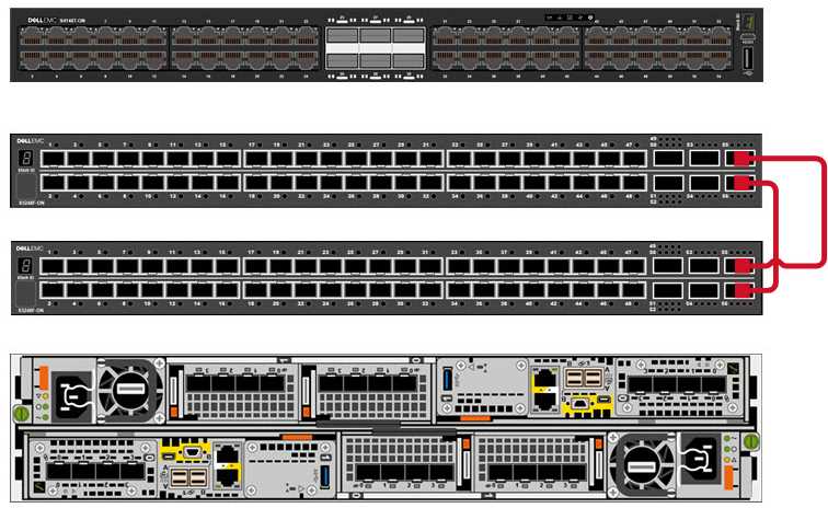
Refer to the exhibit.
What Dell EMC PowerStore ToR front-end cabling is shown?
- A. VLT interconnectivity
- B. OOB Management
- C. Management and discovery
- D. Core switch uplink
Answer:
A
Question 12
What describes Dell EMC PowerStore X front-end cabling?
- A. Uses internal VMware virtual switching and does not require a management network
- B. Management and discovery use the same cables and connections as storage
- C. Storage and management use the same LACP bonded cable connection
- D. Uses VLTi data switch interconnectivity to support vMotion networks
Answer:
B
Explanation:
The Dell EMC PowerStore X series supports Ethernet connectivity through ports on the embedded
module, and on optional I/O modules1
. This design allows for management and discovery to use the
same cables and connections as storage.
The PowerStore X models support front-end NVMe
connectivity with NVMe over Fibre Channel and NVMe over TCP, providing a complete end-to-end
NVMe solution2
.
For the PowerStore X, the management network is integrated with the storage network, which
simplifies the cabling requirements and reduces the number of separate networks that need to be
maintained.
This integration is particularly beneficial in VMware environments where the
PowerStore X can leverage internal VMware virtual switching, which further streamlines the network
infrastructure1
.
In summary, the front-end cabling of the Dell EMC PowerStore X is designed to consolidate
management and storage networking, which simplifies the overall network design and reduces the
complexity of cable management.
This approach is aligned with best practices for storage
connectivity and ensures efficient use of network resources3
.
Question 13
How is a defective embedded module displayed in Dell EMC PowerStore Manager?
- A. Blue with a faulted state
- B. Orange with a faulted state
- C. Orange with an empty state
- D. Blue with an empty state
Answer:
B
Explanation:
In Dell EMC PowerStore Manager, a defective embedded module is displayed as orange with a
faulted state. This color coding is used to indicate that there is a fault with the embedded module.
The PowerStore Manager provides a visual representation of the system’s health and status, and the
color orange is typically associated with a warning or an issue that needs attention.
The procedure for identifying and replacing a faulted embedded module involves using the
PowerStore Manager to locate the faulted component. Once identified, the module displays an
orange LED to indicate its faulted state.
This is part of the system’s design to help administrators
quickly and easily identify components that require attention1
.
For detailed instructions on replacing a faulted embedded module or understanding the LED states
for troubleshooting, you can refer to the PowerStore documentation provided by Dell, which
includes comprehensive guides on handling such scenarios2
.
Question 14
When planning for a Dell EMC PowerStore T implementation, what is the minimum number of IP
addresses required for the storage network?
- A. 3
- B. 1
- C. 2
- D. 4
Answer:
C
Explanation:
When planning for a Dell EMC PowerStore T implementation, the minimum number of IP addresses
required for the storage network is two. This is because each PowerStore T appliance requires a
minimum of one IP address per node for the storage network.
Since the PowerStore T model
typically comes with two nodes (Node A and Node B), you will need at least two IP addresses—one
for each node1
.
It’s important to note that while two IP addresses are the minimum requirement, having additional
IP addresses can be beneficial for optimization purposes.
For example, the PowerStore 3000X, 5000X,
7000X, and 9000X models recommend having six IP addresses minimum per appliance for the
storage network, with eight being recommended for optimization2
.
In summary, for a basic PowerStore T setup, two IP addresses are required for the storage network to
accommodate each node within the appliance. However, depending on the specific model and the
scale of your implementation, more IP addresses may be recommended to ensure optimal
performance and management of the storage network.
Question 15
What is the reason for the best practice of leaving 2 Us of space at the bottom of the rack when
racking Dell EMC PowerStore systems?
- A. Provide cooling air intake
- B. Leave room for serviceability
- C. Leave clearance for wheel roll
- D. Provide better rack stability
Answer:
B
Explanation:
The reason for the best practice of leaving 2 Us of space at the bottom of the rack when racking Dell
EMC PowerStore systems is to leave room for serviceability.
When installing a Dell EMC PowerStore system, it is recommended to leave 2 Us of space at the
bottom of the rack.
This space is not for cooling, wheel clearance, or stability, but rather to ensure that there is enough
room for service activities1
.
Serviceability involves the ability to access and maintain hardware components easily. The additional
space allows for better maneuverability and access to the system for maintenance and repairs.
Following this best practice helps in preventing potential issues that might arise from cramped
spaces, which can make it difficult to perform necessary service tasks1
.
For more detailed information on installation best practices, refer to the Dell EMC PowerStore Quick
Start Guide or the Best Practices Guide21
.