dell D-PE-OE-23 Exam Questions
Questions for the D-PE-OE-23 were updated on : Feb 20 ,2026
Page 1 out of 4. Viewing questions 1-15 out of 50
Question 1
SIMULATION
The system administrator cannot boot their R660 server. To help troubleshooting, use the iDRAC
Ul to enable capturing the full POST sequence for the next time it attempts to boot.
Answer:
See the
Explanation for Step
by Step solution.
Explanation:
To enable capturing the full POST (Power-On Self-Test) sequence using the iDRAC interface, follow
these steps:
Step-by-Step Guide:
Log into the iDRAC Interface:
Access the iDRAC UI using the server’s IP address from a web browser.
Enter your credentials to log in.
Navigate to System BIOS Settings:
Go to the Configuration tab on the top menu.
Select BIOS Settings from the dropdown menu. This will take you to the settings where you can
manage BIOS-related configurations.
Enable POST Sequence Logging:
In the BIOS Settings, look for an option related to POST Behavior or Boot Sequence Capture.
Enable Verbose Mode or Capture Full POST Sequence. This setting ensures that the entire POST
process is logged in detail during the next boot attempt.
Alternatively, if there is a specific setting for Capture System Boot Logs, enable it to ensure detailed
logging during POST.
Apply the Changes:
After enabling the POST capture option, click Apply or Save.
iDRAC may prompt for confirmation or inform you that changes will take effect upon the next reboot.
Confirm any prompts as required.
Restart the Server (if necessary):
If the server is currently off, attempt to power it on. If it’s on, you may need to perform a Graceful
Shutdown followed by a restart to initiate the POST sequence.
Review POST Logs After Reboot:
Once the server attempts to boot, return to the iDRAC Logs section to review the captured POST logs.
Go to Maintenance > System Event Log or Lifecycle Log to view the detailed logs from the POST
sequence. This can help diagnose why the server is failing to boot.
By enabling this setting, you will capture detailed information during the POST process, which can
then be reviewed to identify any hardware or configuration issues preventing the server from
booting successfully.
Question 2
SIMULATION
A customer has relocated one of their Dell PowerEdge platform servers from their main data center
to a remote edge location, which uses a different network segment.
Reconfigure the iDRAC network settings with the following information:
. IP Address (CIDR):
192.168.0.120 (/24)
. Gateway: 192.168.0.1
. DNS Server 1: 10.10.0.1
. DNS Server 2: 10.10.0.2
Answer:
See the
Explanation for Step
by Step solution.
Explanation:
To reconfigure the iDRAC network settings with a new IP address, gateway, and DNS servers, follow
these steps in the iDRAC interface:
Step-by-Step Guide:
Access iDRAC Network Settings:
Log into the iDRAC interface.
Go to the iDRAC Settings tab in the top menu.
Select Network from the dropdown options. This will open the network configuration page.
Change IP Address and Subnet Mask:
In the Network settings, locate the section for IPv4 Settings.
Set the IP Address to 192.168.0.120.
For the Subnet Mask, since it’s a /24 CIDR, set it to 255.255.255.0.
Configure the Gateway:
In the same section, find the field for Default Gateway.
Enter the Gateway as 192.168.0.1.
Update DNS Server Information:
Scroll down to the DNS Server settings.
Enter DNS Server 1 as 10.10.0.1.
Enter DNS Server 2 as 10.10.0.2.
Apply the Settings:
After entering all the new network information, click on Apply or Save to confirm the changes.
The iDRAC interface may prompt for a restart to apply network changes. Follow any prompts as
needed.
Verify the Configuration:
After applying the changes, check that the iDRAC is accessible at the new IP address 192.168.0.120.
Confirm that the gateway and DNS settings are properly configured by testing connectivity or
accessing the iDRAC from a device within the same network segment.
By completing these steps, you will have reconfigured the iDRAC network settings for the new
network segment, allowing remote management of the Dell PowerEdge server at the edge location.
Question 3
SIMULATION
Using the iDRAC UI, generate and save locally a SupportAssist collection with system
information and debug logs only.
Answer:
See the
Explanation for Step
by Step solution.
Explanation:
To generate and save a SupportAssist collection with system information and debug logs only in the
iDRAC UI, follow these steps:
Step-by-Step Guide:
Access SupportAssist in iDRAC:
In the iDRAC interface, navigate to the Maintenance tab in the top menu.
From the dropdown, select SupportAssist. This will bring up the SupportAssist options.
Initiate a Collection:
In the SupportAssist section, look for the option to Create a New Collection or Start a Collection.
Choose Collect System Data or Generate a Collection, depending on the version of iDRAC.
Select Collection Components:
When prompted to select components for the collection, check the boxes for System Information and
Debug Logs only.
Ensure no other components are selected to limit the collection to just the required data.
Start the Collection:
Confirm your selection, then click Start or Generate. This will initiate the process to gather the
specified data from the system.
Save the Collection Locally:
Once the collection is complete, you should see an option to Download or Save the file.
Click the download link and save the collection file locally on your computer.
Verify the Collection File:
Check the downloaded file to ensure it contains only the system information and debug logs. It
should be in a format such as ZIP or TAR, depending on the system configuration.
By following these steps, you can successfully generate a SupportAssist collection with just the
system information and debug logs and save it to your local system for further review or support
purposes.
Question 4
SIMULATION
Due to recent security breaches and to avoid accidental changes made by the junior IT staff, an
administrator would like to prevent unwanted configuration changes in the iDRAC UI.
Answer:
See the
Explanation for Step
by Step solution.
Explanation:
To prevent unwanted configuration changes in the iDRAC UI, you can adjust user roles, permissions,
or enable specific security settings to restrict access for junior IT staff. Here are the steps to secure
the iDRAC configuration:
Step-by-Step Guide:
Access User Settings:
In the iDRAC interface, navigate to iDRAC Settings from the main menu.
Choose User Authentication or Users to manage user accounts and permissions.
Adjust User Roles and Permissions:
Identify the accounts associated with junior IT staff.
For each user account, adjust the role to Read-Only if you want them to have view-only access
without making configuration changes.
Alternatively, set their permissions to exclude configuration changes. This may involve assigning a
custom role with limited access based on your needs.
Enable Configuration Lock (if available):
Some versions of iDRAC offer a Configuration Lock feature, which prevents any configuration changes
until the lock is removed by an administrator.
Navigate to Configuration > System Security or User Authentication, depending on the version, and
enable the Configuration Lock option.
Set Up Two-Factor Authentication (Optional):
For added security, enable Two-Factor Authentication under iDRAC Settings > Network or Security
settings. This step ensures only authorized users can access and make changes to the iDRAC UI.
Save and Apply Security Changes:
After setting up the desired restrictions and permissions, save the settings to apply the changes.
Verify that junior IT staff accounts now have restricted access and cannot make configuration
changes.
Log Out and Test the Changes:
Log out of the administrator account and log in with a junior IT staff account to confirm that the
permissions are set correctly.
Ensure that configuration changes are disabled and that the user can only view the iDRAC interface
as per the restrictions.
By following these steps, you can restrict junior IT staff from making any configuration changes within
the iDRAC interface, thus preventing accidental or unauthorized modifications.
Question 5
The system administrator receives an email notification on April 30, 2022 that a power issue was
reported on the Dell PowerEdge R660. Which log entry helps them investigate this issue for that
date?
- A. Under voltage fault detection on power supply 1.
- B. Power supply 2 has failed.
- C. Under voltage fault detected on power supply 2.
- D. Power supply 1 has failed.
Answer:
C
Explanation:
To investigate a power issue on a specific date, such as April 30, 2022, the system administrator
should examine the iDRAC logs for entries related to power supply faults or failures. Here's how to
approach finding the correct answer:
Step-by-Step Approach:
Access the System Logs:
In the iDRAC interface, navigate to the Dashboard tab.
Scroll down to the Recent Logs section or navigate to System Logs under Maintenance or iDRAC
Settings (depending on the iDRAC version) to access detailed logs.
Filter Logs by Date:
Use the filter option to specify the date, focusing on entries from April 30, 2022. This will help
narrow down relevant events.
Identify Power-Related Entries:
Look for log entries that mention power supply issues or voltage faults around the specified date. In
this case, entries related to under-voltage faults or power supply failures will be critical.
Interpret the Log Entries:
Based on typical power fault logs, consider the possible answers:
A . Under voltage fault detection on power supply 1: Indicates a voltage issue was detected on PSU1.
B . Power supply 2 has failed: Indicates PSU2 has completely failed.
C . Under voltage fault detected on power supply 2: Indicates a voltage issue was detected on PSU2.
D . Power supply 1 has failed: Indicates PSU1 has completely failed.
The specific log entry depends on the exact wording in the logs. However, from the options provided,
if the administrator received a notification about a power issue, the most likely scenario involves a
failure or under-voltage detection.
Question 6
SIMULATION
A customer wants to change the PSU configuration to a 2+0 with PSU2 as the primary. Use the
simulator to complete this task in the iDRAC UI.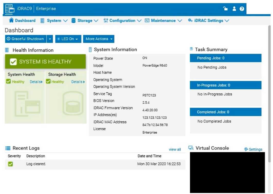
Answer:
See the
Explanation for Step
by Step solution.
Explanation:
To change the Power Supply Unit (PSU) configuration to a 2+0 setup with PSU2 as the primary in the
iDRAC interface, follow these steps:
Step-by-Step Guide:
Navigate to Power Management Settings:
In the iDRAC interface, go to the Configuration tab at the top.
Select Power Management from the dropdown options.
Locate the Power Configuration Section:
Within the Power Management settings, look for a section labeled Power Configuration or Power
Supply Configuration.
Select the Redundancy Policy:
Change the Redundancy Policy to 2+0. In this configuration, there will be no redundancy, and both
power supplies will be active but configured as independent power sources without failover.
Set PSU2 as the Primary PSU:
Locate the option to designate the Primary PSU. Select PSU2 as the primary power source.
This setting ensures that PSU2 will handle the primary power load under normal conditions.
Apply and Save Changes:
Once you have made these changes, click Apply or Save to confirm the new configuration.
The interface may prompt for confirmation, after which the settings will be saved, and PSU2 will
become the primary power supply under a 2+0 configuration.
Verify Configuration:
Review the updated settings to confirm that PSU2 is now set as primary and that the redundancy
policy is 2+0, meaning only PSU2 is actively providing power without a secondary backup.
By following these steps in the iDRAC simulator, you will set up PSU2 as the primary power source
with no redundancy, ensuring a 2+0 configuration. This setup will leverage PSU2 exclusively without
automatic failover to another power supply.
Question 7
SIMULATION
A system administrator is asked to create an iDRAC shared management port using LOM2 and
create a failover network using LOM3. Use the simulator to accomplish this task.
Answer:
See the
Explanation for Step
by Step solution.
Explanation:
To configure an iDRAC shared management port with LOM2 and set up a failover network using
LOM3 in the iDRAC interface, follow these steps:
Step-by-Step Guide:
Access iDRAC Network Settings:
In the iDRAC interface, navigate to the iDRAC Settings tab in the top menu bar.
Select Network from the dropdown options to access network configuration settings.
Configure the Shared Management Port:
In the Network settings, locate the section for Network Interface or LAN Interface Configuration.
Change the NIC Selection to Shared. This will enable the use of a LAN on Motherboard (LOM) port for
iDRAC management.
Select LOM2 for the Shared Management Port:
Once you’ve selected Shared, additional options should appear for selecting the specific port.
Choose LOM2 as the Shared Management Port. This configures iDRAC to use LOM2 for its primary
network connection.
Enable Failover and Select LOM3:
Look for the Failover settings within the same Network Interface configuration.
Enable Failover and select LOM3 as the failover network port. This configuration allows iDRAC to
switch to LOM3 automatically if there is an issue with the connection on LOM2.
Save and Apply Settings:
Once you have configured the shared management port and failover settings, click Apply or Save to
confirm the configuration.
The iDRAC interface may briefly refresh, and you should receive a confirmation that the settings have
been applied successfully.
Verify Configuration:
After the settings are saved, you can verify that LOM2 is listed as the shared management port and
that LOM3 is set as the failover port under Network settings.
By following these steps in the simulator, you should be able to configure iDRAC to use LOM2 for the
shared management port and set up a failover network with LOM3. Make sure to save your changes
to apply the configuration.
Question 8
SIMULATION
An administrator has been tasked to create and save replacement of a server configuration with the
file
name of "PE-server".
The profile must include the configuration for only the following components:
. NIC
. RAID
. iDRAC
Using the simulator, create and save the replacement with these components.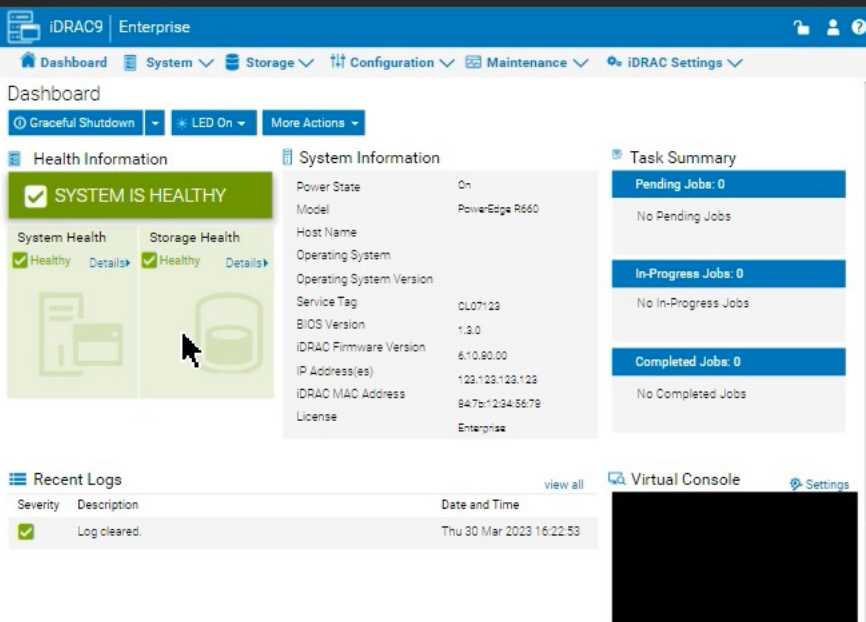
Answer:
See the
Explanation for Step
by Step solution.
Explanation:
To create and save a server configuration profile with specific components in the iDRAC interface,
follow these steps:
Step-by-Step Guide:
Access Configuration Profiles:
Go to the "Configuration" tab on the top menu bar.
From the dropdown options, select "Server Configuration Profile."
Create a New Profile:
Within the Server Configuration Profile section, choose the option to Create a New Profile.
You will likely see options to specify which components to include in the configuration profile.
Select Components:
When prompted, select only the components required for the configuration:
NIC: Network Interface Card settings.
RAID: Storage controller and RAID configuration.
iDRAC: iDRAC management settings.
Ensure that other components are not selected to meet the requirement.
Save the Configuration:
Enter the file name "PE-server" for the profile.
Choose the option to Save or Export the configuration profile. This should save the configuration to
the specified name, typically on the server or local storage available through iDRAC.
Verify the Profile Creation:
After saving, verify that the profile appears in the list of server configuration profiles with the name
"PE-server."
Confirm that it includes only the selected components.
By following these steps, you should successfully create and save the configuration profile with the
specified components.
Question 9
Click the Launch Simulator button.
Using the iDRAC UI, what is listed as the Cache Memory Size for the H965i storage controller?
Note: It is necessary to close (x) the simulator window before you can select a response to this
question.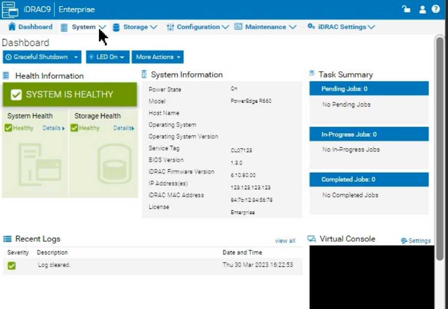
- A. 965 MB
- B. 8361 MB
- C. 1064 MB
- D. 8 GB
Answer:
D
Explanation:
Launch the Simulator:
Open the PowerEdge iDRAC simulator to access the user interface and perform the required task.
Navigate to System Information:
In the top menu bar, select the "Configuration" tab.
From the options that appear, choose "Storage". This section will display details and configurations
for the storage controllers installed on the server.
Check the H965i Storage Controller:
Locate the H965i storage controller in the list. Selecting it should bring up a summary page with
various specifications for the controller.
Look for the field labeled "Cache Memory Size". This will provide the cache memory size value for the
controller.
Question 10
What are the two purposes of E3 EDSFF drives?
(Select 2)
- A. Provides higher interface speed with PCIe Gen4.
- B. Replaces 3.5" and M.2 form factors.
- C. Provides a common form factor for accelerator and computational storage.
- D. Replaces 2.5" and U.2 form factors.
Answer:
C, D
Explanation:
Understanding E3 EDSFF Drives
Server Components (26%)
Define storage options, Drives
What is EDSFF?
Enterprise and Datacenter Storage Form Factor (EDSFF) is a family of SSD form factors designed for
enterprise and data center applications.
E3 Form Factor: A specific size within the EDSFF standard, optimized for performance, density, and
thermal efficiency.
Purposes of E3 EDSFF Drives
Replaces 2.5" and U.2 Form Factors
E3 drives are intended to replace traditional 2.5" SSDs and U.2 form factors.
They offer higher density, improved thermal characteristics, and better scalability.
Conclusion: Option D is Correct
Provides a Common Form Factor for Accelerator and Computational Storage
E3 EDSFF drives are designed to support not only storage but also accelerator devices like GPUs,
FPGAs, and computational storage.
This standardization simplifies system design and improves compatibility.
Conclusion: Option C is Correct
Explanation of Options
Option A: Provides higher interface speed with PCIe Gen4
Analysis: While EDSFF drives do support PCIe Gen4, their primary purpose is form factor
standardization and scalability, not just providing higher interface speeds.
Conclusion: Not the main purpose.
Option B: Replaces 3.5" and M.2 form factors
Analysis: E3 EDSFF does not directly replace 3.5" HDDs or M.2 SSDs, which serve different purposes
and sizes.
Conclusion: Incorrect.
Option C: Provides a common form factor for accelerator and computational storage
Analysis: Correct as per the explanation above.
Conclusion: Correct Answer
Option D: Replaces 2.5" and U.2 form factors
Analysis: Correct as per the explanation above.
Conclusion: Correct Answer
Dell Operate Reference
Server Components (26%)
Define storage options, Drives: Knowledge of new storage technologies and form factors is essential
for modern server configurations.
Server Portfolio and Features (10%)
Identify server features and specifications: Understanding hardware advancements and their
practical benefits.
Conclusion
The E3 EDSFF drives serve to replace traditional 2.5" and U.2 form factors (Option D) and provide a
common form factor for accelerator and computational storage devices (Option C), enhancing
scalability and compatibility in data centers.
Topic 2, PowerEdge Test Simulator
You will need to use the PowerEdge Simulator to correctly answer questions in Part 2. The simulator
allows you to navigate through the PowerEdge interface and configure many items. You will be
scored on your ability to perform tasks, configure items, and gather information within the simulated
environment.
Question 11
A server is experiencing latency issues, and the end user was told to disable C States and C1E.
Where can these settings be checked in the BIOS?
- A. Processor Settings
- B. Miscellaneous Settings
- C. System Profile Settings
- D. System Information
Answer:
C
Explanation:
Locating C States and C1E Settings in the BIOS
System Administration (18%)
Configure BIOS, Storage, virtual media, networking, user access, lockdown mode, and group
management
Understanding C States and C1E
C States: CPU power management features that allow the processor to enter low-power idle states to
conserve energy when idle.
C1E: Enhanced C1 state; a deeper power-saving mode that reduces CPU voltage and frequency.
Impact on Performance
While these features save power, they can introduce latency due to the time required for the CPU to
transition between power states.
Disabling C States and C1E can improve performance and reduce latency, which is crucial for latency-
sensitive applications.
Locating the Settings in BIOS
Enter BIOS Setup
During server startup, press F2 to enter the System Setup (BIOS) utility.
Navigate to System Profile Settings
In the BIOS menu, select System BIOS.
Then select System Profile Settings.
Adjust C States and C1E Settings
Within System Profile Settings, you can:
Set the System Profile to Performance to automatically disable power-saving features.
Manually disable C States and C1E under CPU Power Management if customization is needed.
Explanation of Options
Option A: Processor Settings
Analysis: While this section includes CPU-related configurations, power management settings like C
States and C1E are typically located under System Profile Settings.
Conclusion: Incorrect.
Option B: Miscellaneous Settings
Analysis: This section covers various unrelated settings and does not include CPU power
management options.
Conclusion: Incorrect.
Option C: System Profile Settings
Analysis: This is the correct location for adjusting power management features affecting CPU
performance and latency.
Conclusion: Correct Answer.
Option D: System Information
Analysis: This section displays hardware information and does not allow configuration changes.
Conclusion: Incorrect.
Dell Operate Reference
System Administration (18%)
Configure BIOS: Mastery of BIOS settings is essential for optimizing server performance and
addressing issues like latency.
Server Components (26%)
Define the different processor, memory options, and memory configurations: Understanding how
CPU settings affect overall system performance.
Conclusion
To address latency issues by disabling C States and C1E, the settings can be found and adjusted in the
System Profile Settings section of the BIOS.
Question 12
Exhibit.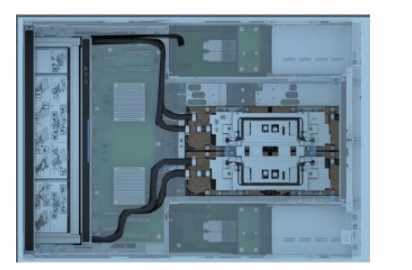
Which two components are displayed in the image?
(Select 2)
- A. Power cables
- B. Paddle card
- C. Cold plates
- D. Leak sensor
Answer:
BC
Explanation:
Identifying Components in the Exhibit
Server Components (26%)
Identify power options and redundancy features, thermal features, and liquid cooling
Analyzing the Image
From the image, the following two components are displayed:
Cold Plates
Cold plates are a key component of liquid cooling systems used in modern servers to dissipate heat
from high-performance components like CPUs and GPUs.
The image shows two prominent cooling structures, which are indicative of cold plates mounted over
processors for efficient heat transfer.
Conclusion: Correct Answer.
Paddle Card
Paddle cards are connectors or adapters used to interface between various server components or
facilitate cable management.
In this image, the paddle card can be seen as part of the interconnect between the cooling system or
main components.
Conclusion: Correct Answer.
Explanation of Other Options
Option A: Power cables
Analysis: There are no visible power cables in the image. The black tubes seen in the image are more
likely part of the liquid cooling system, not power cables.
Conclusion: Incorrect.
Option D: Leak sensor
Analysis: Leak sensors are used in liquid cooling systems to detect leaks, but there are no visible
sensors or specific indicators of leak detection in the image.
Conclusion: Incorrect.
Dell Operate Reference
Server Components (26%)
Define power and thermal options: Recognizing cooling components like cold plates is essential for
understanding server cooling solutions.
Explain expansion cards and their functions: Understanding the purpose of paddle cards helps in
identifying how components connect and function in the server.
Conclusion
The components visible in the image are Cold Plates and Paddle Cards. These are essential parts of
the server's cooling and connectivity systems.
Question 13
What is indicated when the Mid-Bay hard drive LED indicator is solid amber?
- A. Hard Drive has been removed.
- B. Hard Drive temperature is normal.
- C. Hard Drive has lost connectivity with the PERC.
- D. Hard Drive has entered a predictive failure status.
Answer:
C
Explanation:
Understanding Hard Drive LED Indicators in Dell PowerEdge Servers
Server Troubleshooting (32%)
Analyze the visual indicators on server components - system ID, PSU, and BLINK
Overview
Dell PowerEdge servers utilize LED indicators on hard drive carriers to provide immediate visual
feedback on the status of the drives. These indicators are essential for quick diagnostics and
troubleshooting.
Hard Drive LED Indicator Meanings
Typically, the hard drive carrier has two LEDs:
Activity LED (Green): Indicates drive activity (read/write operations).
Status LED (Green/Amber): Indicates the status of the drive.
Status LED Colors and Patterns
Off: Drive is not present or powered off.
Solid Green: Drive is online and functioning normally.
Blinking Green: Drive is being accessed or undergoing initialization.
Blinking Amber: Drive has entered a predictive failure state (SMART alerts).
Solid Amber: Drive has failed or lost connectivity.
Analyzing the Scenario
Solid Amber LED on Mid-Bay Hard Drive: This indicates a critical issue with the drive.
Explanation of Options
Option A: Hard Drive has been removed
Analysis: If the drive is removed, the status LED would be off because there is no power to the drive.
Conclusion: Incorrect.
Option B: Hard Drive temperature is normal
Analysis: A normal temperature would not trigger an amber LED. Temperature warnings are usually
indicated by system alerts or different LED patterns.
Conclusion: Incorrect.
Option C: Hard Drive has lost connectivity with the PERC
Analysis: A solid amber LED often means the drive is not communicating with the RAID controller
(PERC). This could be due to a failed drive or a connectivity issue.
Conclusion: Correct Answer.
Option D: Hard Drive has entered a predictive failure status
Analysis: Predictive failures are typically indicated by a blinking amber LED, warning of impending
drive failure.
Conclusion: Incorrect.
Dell Operate Reference
Server Troubleshooting (32%)
Analyze the visual indicators on server components: Understanding LED indicators is crucial for
diagnosing hardware issues promptly.
Server Components (26%)
Define storage options, Drives, PERC: Knowledge of drive statuses and RAID controller interactions
aids in accurate troubleshooting.
Conclusion
A solid amber LED on the hard drive indicates that the drive has failed or lost connectivity with the
PERC controller. This status requires immediate attention to replace the drive or resolve the
connectivity issue to prevent data loss.
Question 14
The Dell PowerEdge R660 sei /ei is not responding during POST.
What can the system administrator do to enter BIOS progress mode?
- A. Press and hold the power button for 15 seconds.
- B. Enter <F2> when the server tries to POST.
- C. Press and hold the System ID button for more than five seconds.
- D. Disconnect and reconnect the power cables for both PSUs.
Answer:
C
Explanation:
Entering BIOS Progress Mode on a Non-Responsive Dell PowerEdge R660 During POST
Server Troubleshooting (32%)
Explain Configuration Validation, crash capture, and minimum to POST
Analyze the visual indicators on server components - system ID, PSU, and BLINK
Understanding the Scenario
Server Model: Dell PowerEdge R660
Issue: Not responding during POST (Power-On Self-Test)
Objective: Enter BIOS Progress Mode to troubleshoot the issue
What is BIOS Progress Mode?
BIOS Progress Mode is a diagnostic feature that allows the system to display detailed POST codes and
progress indicators during the boot process. This can help administrators identify where the boot
process is stalling.
How to Enter BIOS Progress Mode
Method: Press and hold the System ID button for more than five seconds during the boot process.
Effect:
Forces the server into BIOS Progress Mode.
Displays detailed POST information on the screen.
Helps in diagnosing issues that prevent the server from completing POST.
Explanation of Options
Option A: Press and hold the power button for 15 seconds.
Analysis:
Holding the power button for an extended period typically forces a hard shutdown or initiates a
power reset.
Does not help in entering BIOS Progress Mode.
Conclusion: Incorrect.
Option B: Enter <F2> when the server tries to POST.
Analysis:
Pressing <F2> during POST is the standard method to enter the BIOS Setup Utility.
However, if the server is not responding during POST, this method may not be effective.
Does not specifically enable BIOS Progress Mode.
Conclusion: Less effective.
Option C: Press and hold the System ID button for more than five seconds.
Analysis:
Pressing and holding the System ID button for over five seconds triggers the server to enter BIOS
Progress Mode.
This method is designed for situations where the server is unresponsive during POST.
Conclusion: Correct Answer.
Option D: Disconnect and reconnect the power cables for both PSUs.
Analysis:
Power cycling the server by disconnecting and reconnecting power may not resolve POST issues.
Does not enable BIOS Progress Mode.
Conclusion: Unlikely to help.
Dell Operate Reference
Server Troubleshooting (32%)
Explain Configuration Validation, crash capture, and minimum to POST:
Understanding how to enter BIOS Progress Mode is essential for diagnosing POST-related issues.
Analyze the visual indicators on server components - system ID, PSU, and BLINK:
System ID Button:
Located on the front panel of the server.
Serves multiple functions, including identifying the server in a rack and triggering diagnostic modes.
System Administration (18%)
Configure BIOS, Storage, virtual media, networking, user access, lockdown mode, and group
management:
Familiarity with BIOS access methods and diagnostic tools is crucial for system administrators.
Conclusion
When a Dell PowerEdge R660 server is not responding during POST, pressing and holding the System
ID button for more than five seconds will force the server into BIOS Progress Mode. This allows the
administrator to see detailed POST codes and identify where the boot process is failing.
Question 15
Which attribute is unique to the Lifecycle log?
- A. Message ID
- B. Severity indicator
- C. System event is recorded
- D. Date and timestamp
Answer:
A
Explanation:
Understanding the Unique Attribute of the Lifecycle Log
Server Troubleshooting (32%)
Explain the server logs and memory error
What is the Lifecycle Log?
The Lifecycle Log in Dell PowerEdge servers is a comprehensive log that records system events
related to hardware configuration changes, firmware updates, errors, and other critical information.
It is maintained by the Integrated Dell Remote Access Controller (iDRAC) and provides valuable data
for troubleshooting and auditing.
Unique Attribute of the Lifecycle Log
Message ID:
Each entry in the Lifecycle Log is assigned a unique Message ID.
The Message ID is a specific code that identifies the type of event or error.
These codes are standardized and can be cross-referenced with Dell's documentation to understand
the exact nature of the event.
Uniqueness:
While other logs may include timestamps, severity indicators, and event descriptions, the use of
standardized Message IDs is unique to the Lifecycle Log.
This attribute allows for precise identification and correlation of events across systems.
Explanation of Options
Option A: Message ID
Analysis:
The Message ID is unique to the Lifecycle Log, providing specific identifiers for events.
Conclusion: Correct Answer.
Option B: Severity indicator
Analysis:
Severity indicators (e.g., informational, warning, critical) are common in various system logs.
Not unique to the Lifecycle Log.
Conclusion: Incorrect.
Option C: System event is recorded
Analysis:
Recording system events is a fundamental function of all logs.
Not an attribute unique to the Lifecycle Log.
Conclusion: Incorrect.
Option D: Date and timestamp
Analysis:
Date and timestamp entries are standard in virtually all logs to indicate when events occurred.
Not unique to the Lifecycle Log.
Conclusion: Incorrect.
Dell Operate Reference
Server Troubleshooting (32%)
Explain the server logs and memory error:
Understanding the structure and attributes of the Lifecycle Log is essential for effective
troubleshooting.
Recognizing the importance of Message IDs aids in diagnosing and resolving issues quickly.
Server Management and Configuration Tools (14%)
Explain the management interface options - LCC, racadm, OMSA, iSM, OME:
The Lifecycle Controller (LCC) and iDRAC provide access to the Lifecycle Log and its detailed entries.
Conclusion
The Message ID is the attribute unique to the Lifecycle Log. It allows administrators to identify and
interpret specific events accurately, facilitating efficient troubleshooting and system management.