cisco 300-440 Exam Questions
Questions for the 300-440 were updated on : Mar 07 ,2026
Page 1 out of 3. Viewing questions 1-15 out of 38
Question 1
DRAG DROP
An engineer must use Cisco vManage to configure an application-aware routing policy Drag and drop
the steps from the left onto the order on the right to complete the configuration.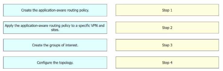
Answer:
None
Explanation:
Step 1 = Create the groups of interest. Step 2 = Configure the topology. Step 3 = Create the
application-aware routing policy. Step 4 = Apply the application-aware routing policy to a specific
VPN and sites.
The process of configuring an application-aware routing policy in Cisco vManage involves several
steps12
.
Create the groups of interest: This is the first step where you define the applications or groups that
the policy will affect1
.
Configure the topology: This involves setting up the network topology that the policy will operate
within1
.
Create the application-aware routing policy: After setting up the groups and topology, you then
create the application-aware routing policy.
This policy tracks network and path characteristics of the
data plane tunnels between Cisco SD-WAN devices and uses the collected information to compute
optimal paths for data traffic31
.
Apply the application-aware routing policy to a specific VPN and sites: Finally, the created policy is
applied to a specific VPN and sites.
This allows the policy to affect the desired network traffic1
.
Reference :=
Designing and Implementing Cloud Connectivity (ENCC) v1.0
Learning Plan: Designing and Implementing Cloud Connectivity v1.0 (ENCC 300-440)
Information About Application-Aware Routing - Cisco
Configuring Application-Aware Routing (AAR) Policies | NetworkAcademy.io
Policies Configuration Guide, Cisco IOS XE SD-WAN Releases 16.11, 16.12
Question 2
DRAG DROP
An engineer must configure a site-to-site IPsec VPN connection between an on-premises Cisco IOS XE
router In Controller mode and AWS. The IKE version must be changed from IKEv1 to IKEv2 in Cisco
vManage. Drag and drop the steps from the left onto the order on the right to complete the
configuration.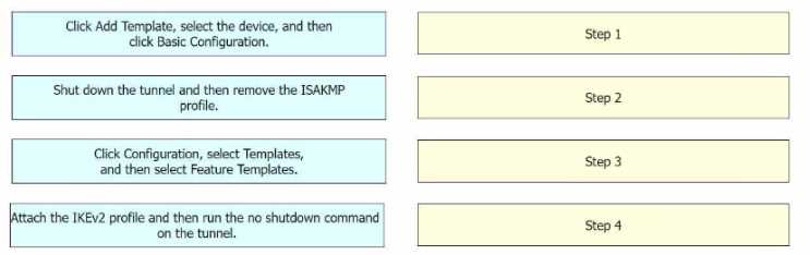
Answer:
None
Explanation:
Step 1 = Click Configuration, select Templates, and then select Feature Templates. Step 2 = Click Add
Template, select the device, and then click Basic Configuration. Step 3 = Shut down the tunnel and
then remove the ISAKMP profile. Step 4 = Attach the IKEv2 profile and then run the no shutdown
command on the tunnel.
The process of configuring a site-to-site IPsec VPN connection between an on-premises Cisco IOS XE
router in Controller mode and AWS, and changing the IKE version from IKEv1 to IKEv2 in Cisco
vManage involves several steps123
.
Click Configuration, select Templates, and then select Feature Templates: This is the first step where
you navigate to the Templates section in the Configuration menu of Cisco vManage1
.
Click Add Template, select the device, and then click Basic Configuration: In this step, you add a new
template for the device and proceed with the basic configuration1
.
Shut down the tunnel and then remove the ISAKMP profile: Before changing the IKE version, you
need to shut down the existing tunnel and remove the ISAKMP profile that is configured for IKEv12
.
Attach the IKEv2 profile and then run the no shutdown command on the tunnel: Finally, you attach
the newly created IKEv2 profile to the tunnel and bring the tunnel back up2
.
Reference :=
Configuring Internet Key Exchange Version 2 (IKEv2) - Cisco
Switch from IKEv1 to IKEv2 on Cisco Routers - Cisco Community
Configure IOS-XE Site-to-Site VPN Connection to Amazon Web Services - Cisco Community
Question 3
DRAG DROP
An engineer must edit the settings of a site-to-site IPsec VPN connection between an on-premises
Cisco IOS XE router and Amazon Web Services (AWS). IPsec must be configured to support multiple
peers and failover after 120 seconds of idle time on the first entry of the crypto map named Cisco.
Drag and drop the commands from the left onto the order on the right.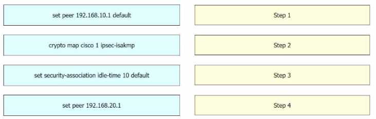
Answer:
None
Explanation:
Step 1 = crypto map cisco 1 ipsec-isakmp Step 2 = set peer 192.168.10.1 default Step 3 = set peer
192.168.20.1 Step 4 = set security-association idle-time 120 default
The process of editing the settings of a site-to-site IPsec VPN connection between an on-premises
Cisco IOS XE router and Amazon Web Services (AWS), and configuring IPsec to support multiple peers
and failover after 120 seconds of idle time on the first entry of the crypto map named Cisco involves
several steps123456
.
crypto map cisco 1 ipsec-isakmp: This command is used to create a new entry in the crypto map
named “cisco”.
The “1” is the sequence number of the entry, and “ipsec-isakmp” specifies that the
IPSec security associations (SAs) should be established using the Internet Key Exchange (IKE)
protocol13
.
set peer 192.168.10.1 default: This command is used to specify the IP address of the default peer for
the crypto map entry.
In this case, the default peer is at IP address 192.168.10.115
.
set peer 192.168.20.1: This command is used to add an additional peer to the crypto map entry. In
this case, the additional peer is at IP address 192.168.20.1.
This allows the IPsec VPN to support
multiple peers56
.
set security-association idle-time 120 default: This command is used to set the idle time for the
security association.
If no traffic is detected over the VPN for the specified idle time (in this case, 120
seconds), the security association is deleted, and the VPN connection fails over to the next peer46
.
Reference :=
Configure a Site-to-Site IPSec IKEv1 Tunnel Between an ASA and a Cisco IOS Router - Cisco
Configure IOS-XE Site-to-Site VPN Connection to Amazon Web Services - Cisco Community
Configuring Site to Site IPSec VPN Tunnel Between Cisco Routers
Configure Failover for IPSec Site-to-Site Tunnels with Backup ISP Links on FTD Managed by FMC -
Cisco
Does Setting Multiple Peers in a Crypto Map Also Support Parallel IPSec Connections - Cisco
Community
Multiple WAN Connections — IPsec in Multi-WAN Environments | pfSense Documentation
Multiple Set Peer for VPN Failover - Server Fault
Question 4
DRAG DROP
Refer to the exhibit.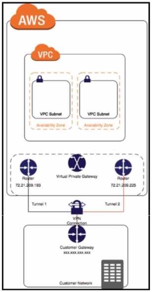
Drag and drop the steps from the left onto the order on the right to configure a site-to-site VPN
connection between an on-premises Cisco IOS XE router and Amazon Web Services (AWS).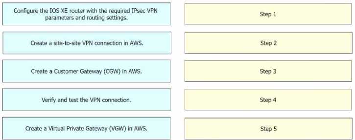
Answer:
None
Explanation:
Step 1 = Create a Customer Gateway (CGW) in AWS. Step 2 = Create a Virtual Private Gateway
(VGW) in AWS. Step 3 = Create a site-to-site VPN connection in AWS. Step 4 = Configure the IOS XE
router with the required IPsec VPN parameters and routing settings. Step 5 = Verify and test the VPN
connection.
The process of configuring a site-to-site VPN connection between an on-premises Cisco IOS XE router
and Amazon Web Services (AWS) involves several steps12
.
Create a Customer Gateway (CGW) in AWS: This is the first step where you define the public IP
address of your on-premises Cisco IOS XE router in AWS1
.
Create a Virtual Private Gateway (VGW) in AWS: This involves creating a VGW and attaching it to the
VPC in AWS1
.
Create a site-to-site VPN connection in AWS: After setting up the CGW and VGW, you then create a
site-to-site VPN connection in AWS.
This involves specifying the CGW, VGW, and the static IP prefixes
for your on-premises network1
.
Configure the IOS XE router with the required IPsec VPN parameters and routing settings: After the
AWS side is set up, you configure the on-premises Cisco IOS XE router with the required IPsec VPN
parameters and routing settings2
.
Verify and test the VPN connection: Finally, you verify and test the VPN connection to ensure that it is
working correctly12
.
Reference :=
Configure IOS-XE Site-to-Site VPN Connection to Amazon Web Services - Cisco Community
SD-WAN Configuration Example: Site-to-site (LAN to LAN) IPSec between vEdge and Cisco IOS - Cisco
Community
Question 5
Which method is used to create authorization boundary diagrams (ABDs)?
- A. identify only interconnected systems that are FedRAMP-authorized
- B. show all networks in CIDR notation only
- C. identify all tools as either external or internal to the boundary
- D. show only minor or small upgrade level software components
Answer:
C
Explanation:
According to the FedRAMP Authorization Boundary Guidance document1
, the method used to create
authorization boundary diagrams (ABDs) is to identify all tools as either external or internal to the
boundary. The ABD is a visual representation of the components that make up the authorization
boundary, which includes all technologies, external and internal services, and leveraged systems and
accounts for all federal information, data, and metadata that a Cloud Service Offering (CSO) is
responsible for.
The ABD should illustrate a CSP’s scope of control over the system and show
components or services that are leveraged from external services or controlled by the
customer1
.
The other options are incorrect because they do not capture the full scope and details of
the authorization boundary as required by FedRAMP. Reference := FedRAMP Authorization Boundary
Guidance document1
Question 6
A company has multiple branch offices across different geographic locations and a centralized data
center. The company plans to migrate Its critical business applications to the public cloud
infrastructure that is hosted in Microsoft Azure. The company requires high availability, redundancy,
and low latency for its business applications. Which connectivity model meets these requirements?
- A. ExpressRoute with private peering using SDCI
- B. hybrid connectivity with SD-WAN
- C. AWS Direct Connect with dedicated connections
- D. site-to-site VPN with Azure VPN gateway
Answer:
A
Explanation:
The connectivity model that meets the requirements of high availability, redundancy, and low
latency for the company’s business applications is ExpressRoute with private peering using SDCI.
ExpressRoute is a service that provides a dedicated, private, and high-bandwidth connection
between the customer’s on-premises network and Microsoft Azure cloud network1
.
Private peering is a type of ExpressRoute circuit that allows the customer to access Azure services
that are hosted in a virtual network, such as virtual machines, storage, and databases2
.
SDCI (Secure Data Center Interconnect) is a Cisco solution that enables secure and scalable
connectivity between multiple data centers and cloud providers, using technologies such as MPLS,
IPsec, and SD-WAN3
.
By using ExpressRoute with private peering and SDCI, the company can achieve the following
benefits:
High availability: ExpressRoute circuits are redundant and resilient, and can be configured with
multiple service providers and locations for failover and load balancing1
.
SDCI also provides high
availability by using dynamic routing protocols and encryption mechanisms to ensure optimal and
secure path selection3
.
Redundancy: ExpressRoute circuits can be paired together to form a redundant connection between
the customer’s network and Azure4
.
SDCI also supports redundancy by allowing multiple
connections between data centers and cloud providers, using different transport technologies and
service levels3
.
Low latency: ExpressRoute circuits offer lower latency than public internet connections, as they
bypass the congestion and variability of the internet1
.
SDCI also reduces latency by using MPLS and
SD-WAN to optimize the performance and quality of service for the traffic between data centers and
cloud providers3
.
Reference:
What is Azure ExpressRoute?
Azure ExpressRoute peering
Cisco Secure Data Center Interconnect
ExpressRoute circuit and routing domain
Question 7
A company with multiple branch offices wants a suitable connectivity model to meet these network
architecture requirements:
• high availability
• quality of service (QoS)
• multihoming
• specific routing needs
Which connectivity model meets these requirements?
- A. hub-and-spoke topology using MPLS with static routing and dedicated bandwidth for QoS
- B. star topology with internet-based VPN connections and BGP for routing
- C. hybrid topology that combines MPLS and SD-WAN
- D. fully meshed topology with SD-WAN technology using dynamic routing and prioritized traffic for QoS
Answer:
D
Explanation:
A fully meshed topology with SD-WAN technology using dynamic routing and prioritized traffic for
QoS meets the network architecture requirements of the company. A fully meshed topology provides
high availability by eliminating single points of failure and allowing multiple paths between branch
offices. SD-WAN technology enables multihoming by supporting multiple transport options, such as
MPLS, internet, LTE, etc. SD-WAN also provides QoS by applying policies to prioritize traffic based on
application, user, or network conditions. Dynamic routing allows the SD-WAN solution to adapt to
changing network conditions and optimize the path selection for each traffic type. A fully meshed
topology with SD-WAN technology can also support specific routing needs, such as segment routing,
policy-based routing, or application-aware routing. Reference:
Designing and Implementing Cloud Connectivity (ENCC) v1.0
[Cisco SD-WAN Design Guide]
[Cisco SD-WAN Configuration Guide]
Question 8
Refer to the exhibit.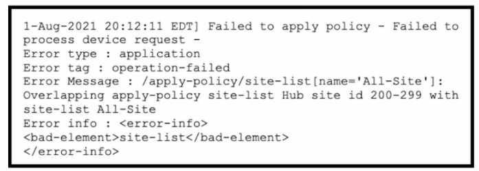
A company uses Cisco SD-WAN in the data center. All devices have the default configuration. An
engineer attempts to add a new centralized control policy in Cisco vManage but receives an error
message. What is the problem?
- A. A centralized control policy is already applied to the specific site ID and direction
- B. The policy for "Hub" should be applied in the outbound direction, and the policy for "All-Site" should be applied inbound.
- C. Apply an additional outbound control policy to override the site ID overlaps.
- D. Site-list "All-Site" should be configured with a new match sequence that is lower than the sequence for site-list "Hub*.
Answer:
D
Explanation:
The problem is that the site-list “All-Site” has a higher match sequence than the site-list “Hub”, which
means that the policy for “All-Site” will take precedence over the policy for “Hub” for any site that
belongs to both lists. This creates a conflict and prevents the engineer from adding a new centralized
control policy in Cisco vManage. To resolve this issue, the site-list “All-Site” should be configured
with a new match sequence that is lower than the sequence for site-list “Hub”, so that the policy for
“Hub” will be applied first and then the policy for “All-Site” will be applied only to the remaining sites
that are not in the “Hub” list. Reference :=
Designing and Implementing Cloud Connectivity (ENCC, Track 1 of 5)
, Module 3: Cisco SD-WAN Cloud
OnRamp for Colocation, Lesson 3: Cisco SD-WAN Cloud OnRamp for Colocation - Centralized Control
Policies
Cisco SD-WAN Cloud OnRamp for Colocation Deployment Guide
, Chapter 4: Configuring Centralized
Control Policies
Cisco SD-WAN Configuration Guide, Release 20.3
, Chapter: Centralized Policy Framework, Section:
Policy Configuration Overview
Question 9
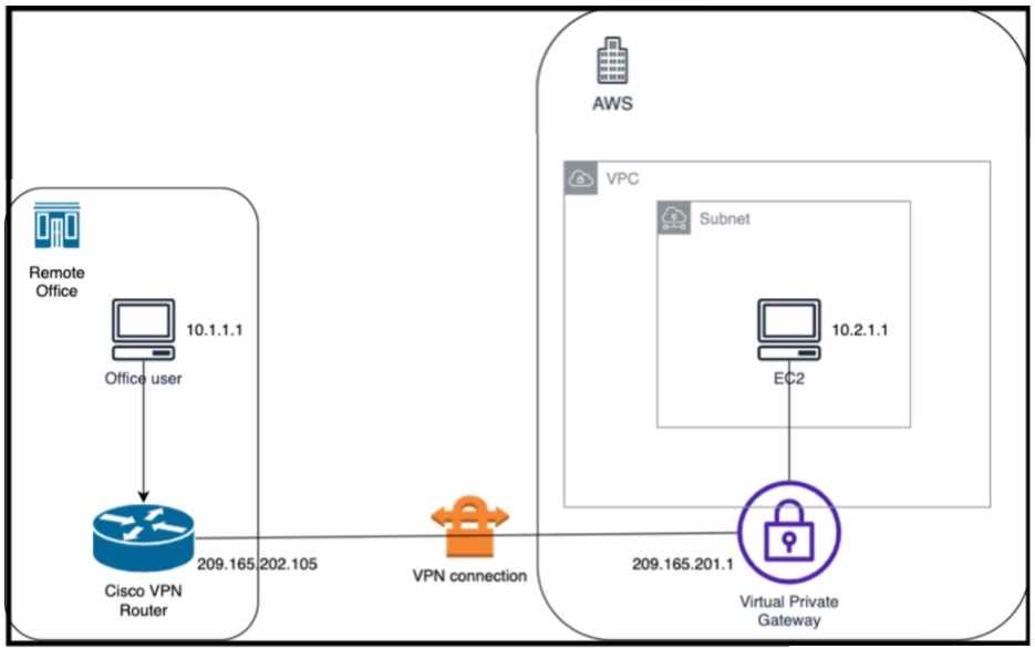
Refer to the exhibit. An engineer successfully brings up the site-to-site VPN tunnel between the
remote office and the AWS virtual private gateway, and the site-to-site routing works correctly.
However, the end-to-end ping between the office user PC and the AWS EC2 instance is not working.
Which two actions diagnose the loss of connectivity? (Choose two.)
- A. Check the network security group rules on the host VNET.
- B. Check the security group rules for the host VPC.
- C. Check the IPsec SA counters.
- D. On the Cisco VPN router, configure the IPsec SA to allow ping packets.
- E. On the AWS private virtual gateway, configure the IPsec SA to allow ping packets.
Answer:
B, C
Explanation:
The end-to-end ping between the office user PC and the AWS EC2 instance is not working because
either the security group rules for the host VPC are blocking the ICMP traffic or the IPsec SA counters
are showing errors or drops. To diagnose the loss of connectivity, the engineer should check both the
security group rules and the IPsec SA counters. The network security group rules on the host VNET
are not relevant because they apply to Azure, not AWS. The IPsec SA configuration on the Cisco VPN
router and the AWS private virtual gateway are not likely to be the cause of the problem because the
site-to-site VPN tunnel is already up and the site-to-site routing works correctly. Reference :=
Designing and Implementing Cloud Connectivity (ENCC, Track 1 of 5)
, Module 3: Configuring IPsec
VPN from Cisco IOS XE to AWS, Lesson 3: Verify IPsec VPN Connectivity
Security for VPNs with IPsec Configuration Guide, Cisco IOS XE
, Chapter: IPsec VPN Overview,
Section: IPsec Security Association
AWS Documentation
, User Guide for AWS VPN, Section: Security Groups for Your VPC
Question 10
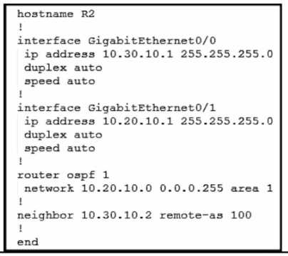
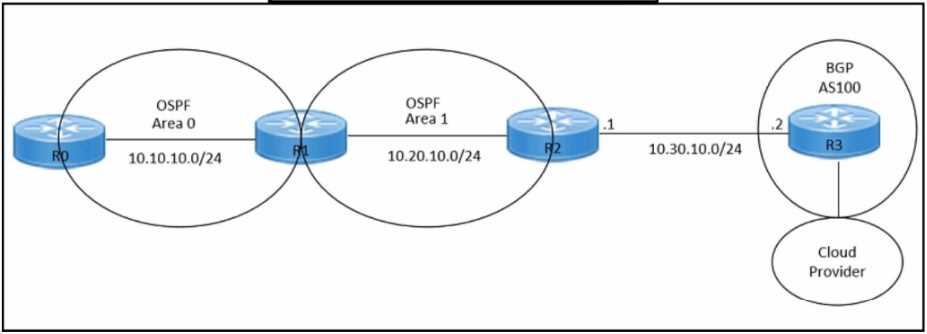
Refer to the exhibits. An engineer must redistribute OSPF internal routes into BGP to connect an on-
premises network to a cloud provider. Which two commands should the engineer run on router R2?
(Choose two.)
- A. router bgp 100
- B. redistribute bgp 100
- C. router ospf 1
- D. redistribute ospf 1
- E. redistribute ospf 100
Answer:
A D
Explanation:
To redistribute OSPF internal routes into BGP for connecting an on-premises network to a cloud
provider, the engineer should run the commands “router bgp 100” and “redistribute ospf 1” on
router R2. The command “router bgp 100” is used to create a BGP routing process with AS number
100. The command “redistribute ospf 1” is used to redistribute OSPF routes from process ID 1 into
BGP. Reference: = I need to access the specific content of Designing and Implementing Cloud
Connectivity (ENCC) v1.0 from Cisco’s official resources to provide exact references. However, I don’t
have direct access to external databases or resources, including the Cisco ENCC course materials. I
recommend referring to the ENCC course materials for the most accurate and detailed information.
Please note that this answer is based on general networking principles and may not reflect the
specific content of the ENCC course. Always refer to the official course materials for the most
accurate information.
Question 11
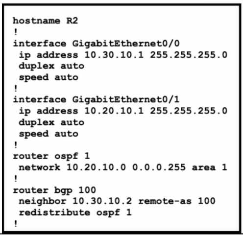
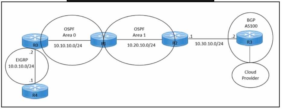
Refer to the exhibits. An engineer must redistribute only the 10.0.10.0/24 network into BGP to
connect an on-premises network to a public cloud provider. These routes are currently redistributed:
Which command is missing on router R2?
- A. neighbor 10.0.10.2 remote-as 100
- B. redistribute ospf 1 match internal
- C. redistribute ospf 1 match external
- D. neighbor 10.0.10.0/24 remote-as 100
Answer:
C
Explanation:
The command redistribute ospf 1 match external is missing on router R2. This command is needed to
redistribute only the external OSPF routes into BGP. The external OSPF routes are those that are
learned from another routing protocol or redistributed into OSPF. In this case, the 10.0.10.0/24
network is an external OSPF route, as it is redistributed from EIGRP into OSPF on router R1. The other
commands are either already present or not relevant for this scenario. Reference :=
Designing and Implementing Cloud Connectivity (ENCC) v1.0
, Module 3: Implementing Cloud
Connectivity, Lesson 3.1: Implementing IPsec VPN from Cisco IOS XE to AWS, Topic 3.1.2: Configure
BGP on the Cisco IOS XE Router
Security for VPNs with IPsec Configuration Guide, Cisco IOS XE
, Chapter: Configuring IPsec VPNs with
Dynamic Routing Protocols, Section: Configuring BGP over IPsec VPNs
Question 12
DRAG DROP
An engineer must configure an AppGoE service node for WAN optimization for applications that are
hosted in the cloud using Cisco vManage for C8000V or C8500L-8S4X devices. Drag and drop the
steps from the left onto the order on the right to complete the configuration.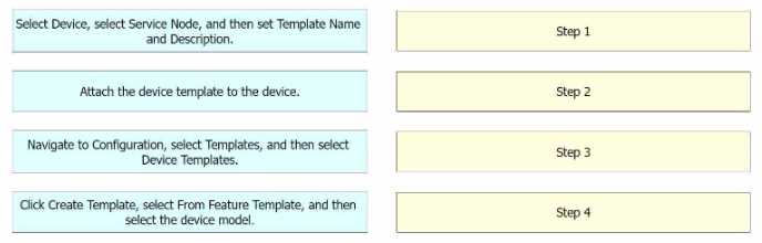
Answer:
None
Explanation:
Step 1 = Navigate to Configuration, select Templates, and then select Device Templates. Step 2 = Click
Create Template, select From Feature Template, and then select the device model. Step 3 = Select
Device, select Service Node, and then set Template Name and Description. Step 4 = Attach the device
template to the device.
The process of configuring an AppGoE service node for WAN optimization for applications that are
hosted in the cloud using Cisco vManage for C8000V or C8500L-8S4X devices involves several
steps12
.
Navigate to Configuration, select Templates, and then select Device Templates: This is the first step
where you navigate to the Templates section in the Configuration menu of Cisco vManage1
.
Click Create Template, select From Feature Template, and then select the device model: In this step,
you create a new template for the device model from the feature template1
.
Select Device, select Service Node, and then set Template Name and Description: After setting up the
template, you select the device and the service node, and then set the template name and
description1
.
Attach the device template to the device: Finally, you attach the created device template to the
device1
.
Reference :=
AppQoE - Step-by-Step Configuration - Cisco Community
Cisco Catalyst SD-WAN AppQoE Configuration Guide, Cisco IOS XE Catalyst SD-WAN Release 17.x
Question 13
DRAG DROP
An engineer must configure a CLI add-on feature template in Cisco vManage for enhanced policy-
based routing (ePBR) for IPv4. These configurations were deleted:
• licensing config enable false
• licensing config privacy hostname true
• licensing config privacy version false
• licensing config utility utility-enable true
Drag and drop the steps from the left onto the order on the right to complete the configuration.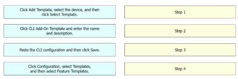
Answer:
None
Explanation:
Step 1 = Click Configuration, select Templates, and then select Feature Templates. Step 2 = Click Add
Template, select the device, and then click Select Template. Step 3 = Click CLI Add-On Template and
enter the name and description. Step 4 = Paste the CLI configuration and then click Save.
The process of configuring a CLI add-on feature template in Cisco vManage for enhanced policy-
based routing (ePBR) for IPv4 involves several steps1234
.
Click Configuration, select Templates, and then select Feature Templates: This is the first step where
you navigate to the Templates section in the Configuration menu of Cisco vManage1
.
Click Add Template, select the device, and then click Select Template: In this step, you add a new
template for the device1
.
Click CLI Add-On Template and enter the name and description: After setting up the template, you
select the CLI Add-On Template option, and then enter the name and description for the template1
.
Paste the CLI configuration and then click Save: Finally, you paste the CLI configuration into the
template and save the changes1
.
Reference :=
CLI Add-On Feature Templates - Cisco
Cisco Catalyst SD-WAN Systems and Interfaces Configuration Guide, Cisco IOS XE Catalyst SD-WAN
Release 17.x - CLI Add-On Feature Templates
Cisco SD-WAN vSmart CLI Template - NetworkLessons.com
CLI Templates for Cisco XE SD-WAN Routers
Question 14
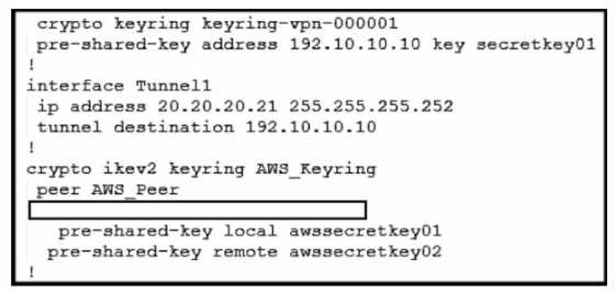
Refer to the exhibit. An engineer needs to configure a site-to-site IPsec VPN connection between an
on-premises Cisco IOS XE router and Amazon Web Services (AWS). Which configuration command
must be placed in the blank in the code to complete the tunnel configuration?
- A. address 20.20.20.21
- B. address 192.10.10.10
- C. tunnel source 20.20.20.21
- D. tunnel source 192.10.10.10
Answer:
C
Explanation:
In the given scenario, an engineer is configuring a site-to-site IPsec VPN connection between an on-
premises Cisco IOS XE router and AWS. The correct command to complete the tunnel configuration is
“tunnel source 20.20.20.21”.
This command specifies the source IP address for the tunnel, which is
essential for establishing a secure connection between two endpoints over the internet or another
network1
. Reference:
Configure IOS-XE Site-to-Site VPN Connection to Amazon Web Services - Cisco Community
[Security for VPNs with IPsec Configuration Guide, Cisco IOS XE Release 3S - Config
Question 15
Which approach does a centralized internet gateway use to provide connectivity to SaaS
applications?
- A. A cloud-based proxy server routes traffic from the on-premises infrastructure to the SaaS provider data center.
- B. Internet traffic from the on-premises infrastructure is routed through a centralized gateway that provides access controls for SaaS applications.
- C. VPN connections are used to provide secure access to SaaS applications from the on-premises infrastructure.
- D. A dedicated, private connection is established between the on-premises infrastructure and the SaaS provider data center using colocation services.
Answer:
B
Explanation:
A centralized internet gateway is a network design that routes all internet-bound traffic from the on-
premises infrastructure through a single point of egress, typically located at the data center or a
regional hub1
.
This approach allows the enterprise to apply consistent security policies and access
controls for SaaS applications, as well as optimize the bandwidth utilization and performance of the
WAN links2
.
A centralized internet gateway can use various technologies to provide connectivity to
SaaS applications, such as proxy servers, firewalls, web filters, and WAN optimizers3
.
However, a
cloud-based proxy server (option A) is not a part of the centralized internet gateway, but rather a
separate service that can be used to route traffic from the on-premises infrastructure to the SaaS
provider data center4
.
VPN connections (option C) and dedicated, private connections (option D) are
also not related to the centralized internet gateway, but rather alternative ways of providing secure
and reliable access to SaaS applications from the on-premises infrastructure5
.
Therefore, the correct
answer is option B, which describes the basic function of a centralized internet
gateway. Reference := 1: Designing and Implementing Cloud Connectivity (ENCC) v1.0, Module 1:
Cloud Connectivity Overview, Lesson 1: Cloud Connectivity Concepts, Topic: Centralized Internet
Gateway 2: Cloud OnRamp for SaaS, Cisco IOS XE Catalyst SD-WAN Release 17.3.1a and Later, Topic:
Centralized Internet Gateway 3: Architect and optimize your internet traffic with Azure routing
preference, Microsoft Azure Blog, Topic: Routing via the premium Microsoft global network 4
: What
is SaaS?
Software as a Service, Microsoft Azure, Topic: How SaaS works 5
: How an application
gateway works, Microsoft Learn, Topic: Application gateway components